evalink ipTNA4i Manuel utilisateur

ipTNA4i
Installationmanual

1
1 Connecting the ipTNA4i 2
2 Commissioning of ipTNA4i 5
Step 1: Capture device via evalink live 5
Step 2: Commissioning 5
Step 3: Transmission test 7
3 Fault diagnostics on the device 8
3.1 Overview of the device state 8
3.2 Select detail status 8
3.3 Fault diagnosis intranet/internet connection 9
3.4 Fault diagnosis mobile connection 9
3.5 Advanced fault diagnosis 10
3.5.1 ipTNA4i as WiFi Access Point 10
3.5.2 Quick test 10
3.5.3 Local congurations 11
4 Installation 11
4.1 Requirements on location 11
4.2 Requirements of the evalink platform 12
4.3 Technical specications 12
Notes and Warnings 13
2
The ipTNA4i reliably transmits alarm conditions from security
systems or error messages from technical installations via TCP/IP to
alarm receiving centres. The encrypted data connections via the
redundant communication paths (Ethernet and Mobile) are regularly
monitored by “Alive-Checks”.
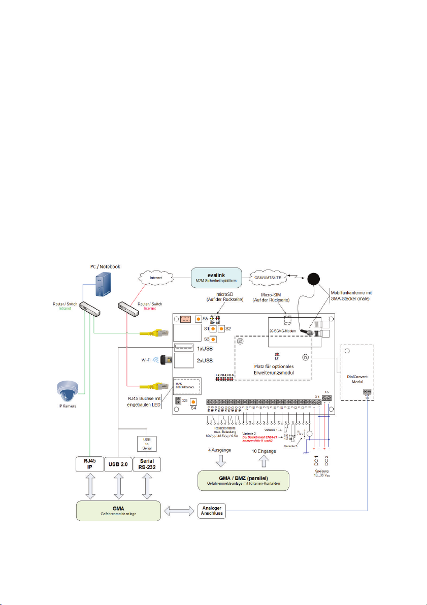
1 Connecting the ipTNA4i
The following explains how to connect the ipTNA4i to a danger alerting system:

3
LAN Connect the network connection (X21, with serial, MAC - number label)
using a shielded patch cable (Cat. 5 STP) to the network (modem,
router or switch).
Antenna Mount the antenna in a suitable location with sufcient reception and
connect the antenna cable to the ipTNA4i SMA connector. The
strength of the cellular signal can be measured with evalink live.
--> Commissioning Step 2
SIM-Card Slide the micro-SIM card into the X6 holder on the rear panel (the
holder is located under the mPCIe modem). The SIM card may not
contain any active PIN code. If necessary, deactivate the PIN using a
mobile phone.
DAS (parallel) Connect the desired I/O terminals with the DAS with cables.
Input Option 1: Unmonitored loop for use with potential-free contact.
Loops open > 50 kΩ / Loops closed < 300 Ω.
Input Option 2: Monitored loop for use with potential-free contact. Only
connect the contact with the indicated resistances. The resistance of
the loop itself must be < 300 Ω. The loop monitoring (to be activated in
evalink) can detect sabotage (short circuit/break the loop).
Input Option 3: Apply external voltage. Uext ≤ 1.5 V: Loop open, Uext ≥
2.5 V: Loop closed. Note the polarity and maximum voltage of 15V.
NOTE: The internal loop power (terminals C) is pulsed and connected
to the potential of the power supply. Wiring of the inputs with
capacitors is not allowed in options 1 and 2. The cable length must not
exceed 100m, screening is recommended.
DAS (Dialler
connection)
Connect the terminal of the optional DialConvert Module with the
analogue port of the danger alerting system.
Supply The ipTNA4i has two power inputs, which are monitored
independently. Connect the terminals X4 and X5 with a DC voltage
source (10-36V DC).
The negative terminals are interconnected as well as connected to the
ground of ipTNA4i.

4
Function
Assignment Description Wiring
Control output Normal use as an output contact with
actuation by evalink. All actuators have been
implemented with bistable relays. This allows
the preservation of the state even if a failure
of both power supplies.
Terminals a - b:
Contact closes
when “true” or “1” is
selected.
Contact opens when
“false” or “0” is
selected.
Fault contact 1
Non-critical Fault
The contact is actuated when the ipTNA4i
detects a fault, but is still operational. A
combined fault has the following causes:
• One of the two power supplies has
failed
• A connection path to evalink Ethernet
or mobile is faulty ¹)
• Mobile reception strength is out of
tolerance (if congured in evalink)
Terminals a - b:
Contact opens in the
event of failure
Fault contact 2
Critical Fault
Mandatory on
output 3
The contact is actuated when the ipTNA4i is
inoperable. A combined fault has the
following causes:
• Both supply inputs are out of tolerance
• No connection to evalink ¹)
Terminals a - c:
Contact opens in the
event of failure
Local alert The contact is activated if a user message
cannot be deduced from any of the
congured targets. ¹)
Terminals a - b:
Contact opens in the
event of failure
DAS (parallel) output port
¹) With congurable delay time. The contact only switches to fault, if the cause still persists
after the delay time has expired.

5
2 Commissioning of ipTNA4i
For easy installation of your device evalink live is available. evalink live independent
of the terminal and can be used on any smartphone, tablet or PC via the browser.
After successful registration under www.evalinklive.com and login on evalink live
please proceed as follows:
Step 1: Capture device via evalink live
Set-up the connection via the online platform www.evalinklive.com.
Step 2: Commissioning
Select the connection and click on Congure.
In the conguration you can see how the device is congured and general
information about the connection can be retrieved.
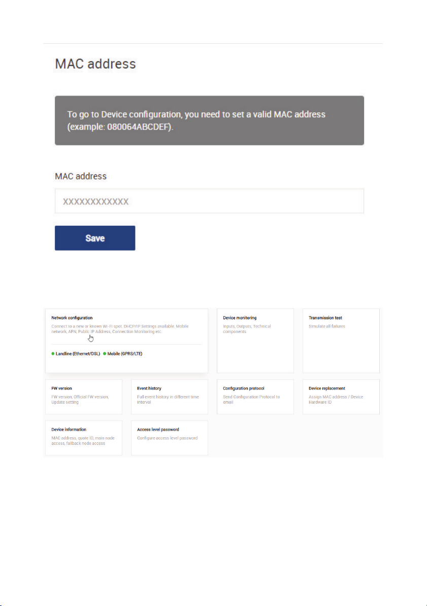
6
You will then be prompted to enter the ipTNA4i MAC address.
Under Check Connection you see the channels through which the device is
connected.
Next, you can check the signal strength by clicking on the mobile (GPRS/LTE) button.
By clicking on the Conguration Log button you can receive the log via email.

7
Step 3: Transmission test
After the successful commissioning of the ipTNA4i, you need to check the
transmission of the individual criteria (I/O) of the danger alerting system to the alarm
receiving centre. The procedure is determined by the responsible operator. Before the
test, the access level passwords must be entered for the ipTNA4i.
Once a connection is available, you can switch to the transmission test.
To start the test, press the SW1 button on the ipTNA4i for 2s.
Now you can test the inputs and outputs, as well as simulate the technical faults.
After the test, you can receive a commissioning certicate via email.

8
3 Fault diagnostics on the device
If commissioning via evalink live was unsuccessful
3.1 Overview of the device state
Once you have entered your device, turn on the power supply. After about 60
seconds, the operating state is achieved. Trouble-free operation is available when the
LEDs adopt the following statuses:
• L2 (operation) flashes slowly
• L3 (Internet connection) remains lit
• L4 (Mobile connection) remains lit
• L5 is not lit
• L6 is not lit
3.2 Select detail status
If the xed network (Ethernet/DSL) or wireless connections could not be established,
you can access additional information about the detail status.
By repeatedly pressing the S3 button, the L2 - L5 are switched to Detail Status (the
specied number of LED applies to fault-free operation).
• Press SW3 1x: GSM signal level - 2 or more LEDs light
• Press SW3 2x: Intranet/Internet connection - L3 - L5
• Press SW3 3x: GSM connection - L3 - L5
• Press SW3 4x: return to the Status Overview
You can also get to back to Status Overview by pressing the SW4 key.
Restart: If you hold the SW3 button down for longer than 6 seconds, the ipTNA4i
reboots.

9
3.3 Fault diagnosis intranet/internet connection
If L3 does not stop flashing:
• Check the LED in the LAN socket. If the LED in the LAN socket is not lit, the
connection to the network (router/switch) is interrupted.
-> Contact the local IT administrator.
• If the LED in the LAN socket lights, press the SW3 button 2x (press 2s, wait 2s,
press 2s), and check the detail status of the Intranet/Internet connection via L2
- L5. If none of these LEDs light, an IP address could not be assigned by the
DHCP
-> Contact the local IT administrator.
• If only L5 is lit, there is a fault with the internet connection (e.g. rewall
• impermeable).
-> Contact the local IT administrator.
• If only L5, L4 and perhaps L3 are lit, the login to evalink has not been successful
-> Contact the operator of the evalink platform
3.4 Fault diagnosis mobile connection
If L4 continues to flash:
• First check that the SIM card is in the correct position.
• Check the signal level and modem status using the InstallerApp. If the reception
is weak, re-position the antenna.
Table des matières
Manuels Système de sécurité populaires d'autres marques


EDM
EDM Solution 6+6 Wireless-AE Manuel utilisateur

Highway Safety Group
Highway Safety Group EA401 Manuel utilisateur

Siren
Siren LED GSM Manuel utilisateur

Detection Systems
Detection Systems 7090i Instructions de montage

Se-Kure Controls
Se-Kure Controls MicroMini SK-4841 Manuel utilisateur

Siemens
Siemens FDM273 Manuel utilisateur