South Bend, Indiana USA | networketi.com ADH INSTRUCTION MANUAL | PART NO.24101 REV B
7
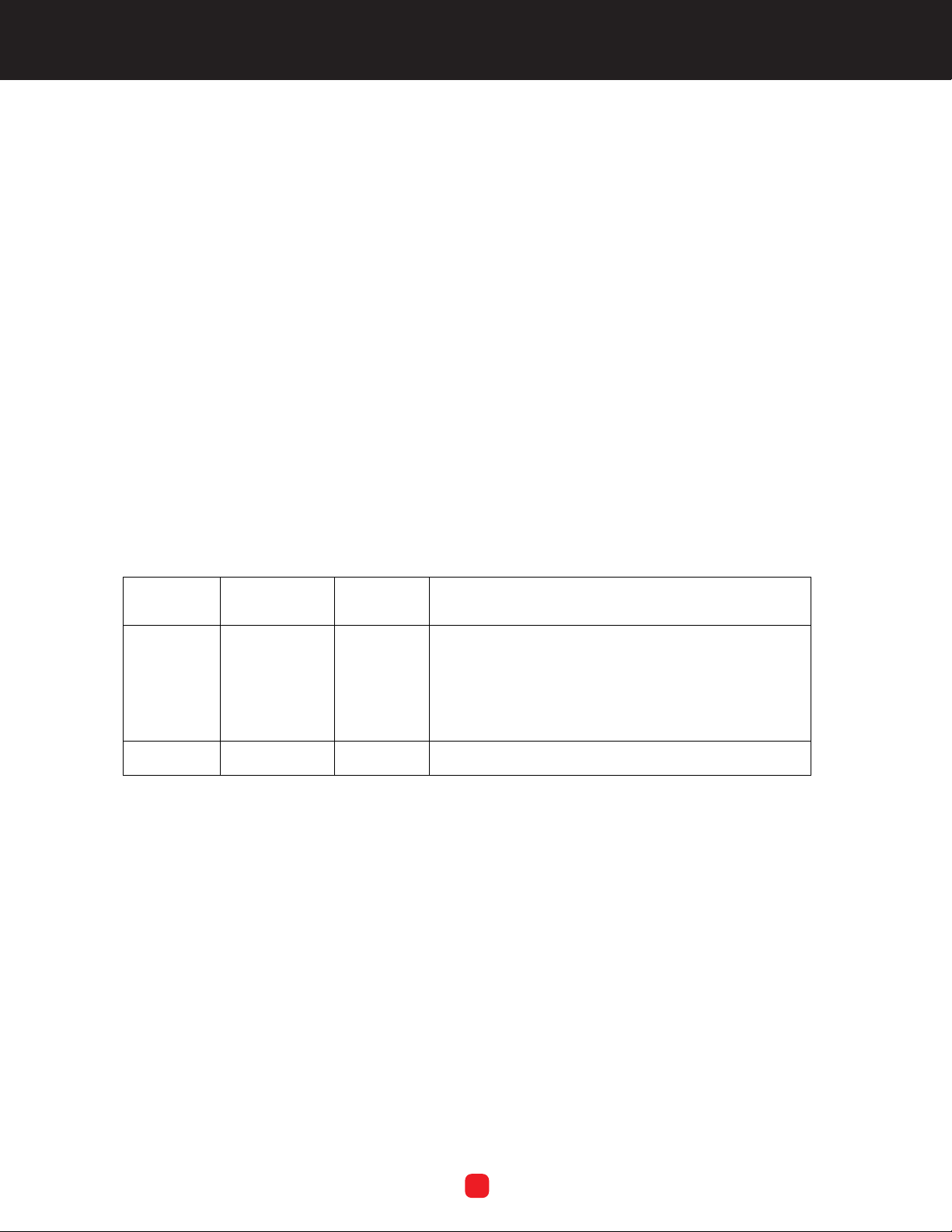
Figure 2. ADH NETCOM AC NEMA
DISCHARGE MANIFOLD.
6. Remove and retain the two screws and
lock washers securing the discharge
manifold to the chassis. With the three
air hoses disconnected and the
mounting hardware removed, take the
existing discharge manifold out of the
machine.
7. Two fittings are included as part of the
replacement kit. These should already
be assembled onto the new manifold.
If not, install the fittings onto the new
manifold as on the original assembly.
To pressure
transducer
From humidity
sensor
To air out
fitting
Safety
Relief Valve
Carefully connect the air hoses to the
new discharge manifold as they had
been connected to the original
manifold. Refer back to Figure 2 on the
previous page. Connect the hose from
the humidity sensor to the fitting in the
middle of the back or top side of the
new discharge manifold. Connect the
hose to the pressure transducer to the
fitting on the left side of the new
discharge manifold. Connect the hose
to the air out fitting to the front or
bottom fitting of the new discharge
manifold. Make sure all hoses
connections are tight.
Reinstall the front cover removed in
step 4 of this section. If it was placed
upside down on the lid of the unit
during this procedure, carefully turn the
cover back over and work it back into
position, past the wires and other
components in the enclosure. Reinstall
the four corner screws securing the
front cover to the chassis.
Reconnect the ground wire by inserting
it behind the retaining screw from
which it was removed, then tighten the
ground wire retaining screw. Reconnect
the green power connector by holding
it in place then tightening the two
captive screws removed in step 3 of this
section. Reconnect both ends of the
orange ethernet cable removed in step
3 of this section. It does not matter
which end of the ethernet cable goes
into which receptacle.
With the ground wire, power connector
and ethernet cable reconnected, close
the lid of the NEMA enclosure and
secure the two latches opposite the
hinges. Secure the lid in place by
reinstalling the two captive screws in
the two outer corners of the lid.
Restore machine power by plugging
the unit back in.
Align the mounting holes of the new
discharge manifold with the Pem®
nuts in the floor of the chassis to which
the original discharge manifold had
been installed. Using the two screws
and lock washers retained in step 6 of
this section, install the new discharge
manifold where the original one had
been, securing the two screws into the
Pem® nuts embedded in the floor of
the chassis. Torque to 8 in/lb.
8.
9.
10.
11.
12.
13.