eSecure ES00M140 Manuel utilisateur

1
User Manual
Model: ES00M140, ES00M180
Version 1.C

2
1 Introduction.................................................................................................................... 3
1.1 Safety Information……………………………………………………………………... 3
1.2 Contents of the box ..............................................................................................3
1.3 Hard disk installation ............................................................................................4
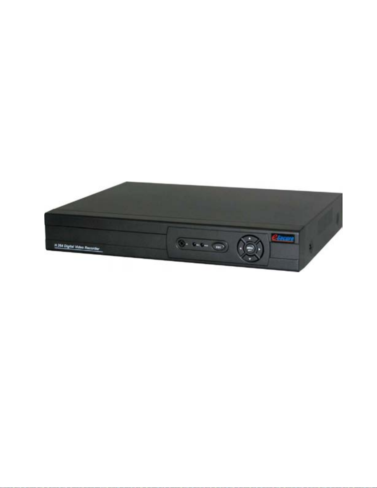
1.4 Front panel........................................................................................................... 4
1.5 Rear panel............................................................................................................5
1.6 Mouse control …………………………………………………………………………5
1.7 Remote Controller Operation…………………………………………………………………….6
1.8 Audio and Video Input/Output Connections……………………………………………………..6
2 Basic operation ……………………………………………………………………………….10
2.2 Login System......................................................................................................11
2.3 Main Menu..........................................................................................................11
2.4 System setup............................................................................................... 14
2.4.1.3 Hard Drive Manage.…………………………………………………………….…16
2.4.2 Account………………………………………………………………………….17
2.4.5 Record ...................................................................................................... 22
2.4.6 Playback and Backup ............................................................................... 25
2.6 Network........................................................................................................ 35
2.7 Web/Remote View....................................................................................... 36
3 Appendix ……………………………………………………………………………………...38
3.1 Network Security Setting……………………………………………………………..38
3.2 Connection Setting .……………………………………………………………..……39
Before You Begin

3
1. Introduction
1.1 Safety Information
•Before setting up the DVR, carefully read all the documentation that came with your package.
•To prevent fire and shock hazard, never expose the DVR to rain or moisture.
•If the power supply is broken, do not try to fix it by yourself. Contact a qualified service
technician or your retailer.
•Before using the product, make sure all cables are correctly connected and the power cables
are not damaged. If you detect any damage, contact your dealer immediately
•The DVR should be operated only by the type of power source indicated on the label. If you
are not sure of the type of power supplied to your home or office, consult your dealer or the
local power company
1.2 Contents of the box
1. DVR device
2. Quick Start Guide
3. CD
4. Remote Control
5. Power and Power cord
6. Mouse
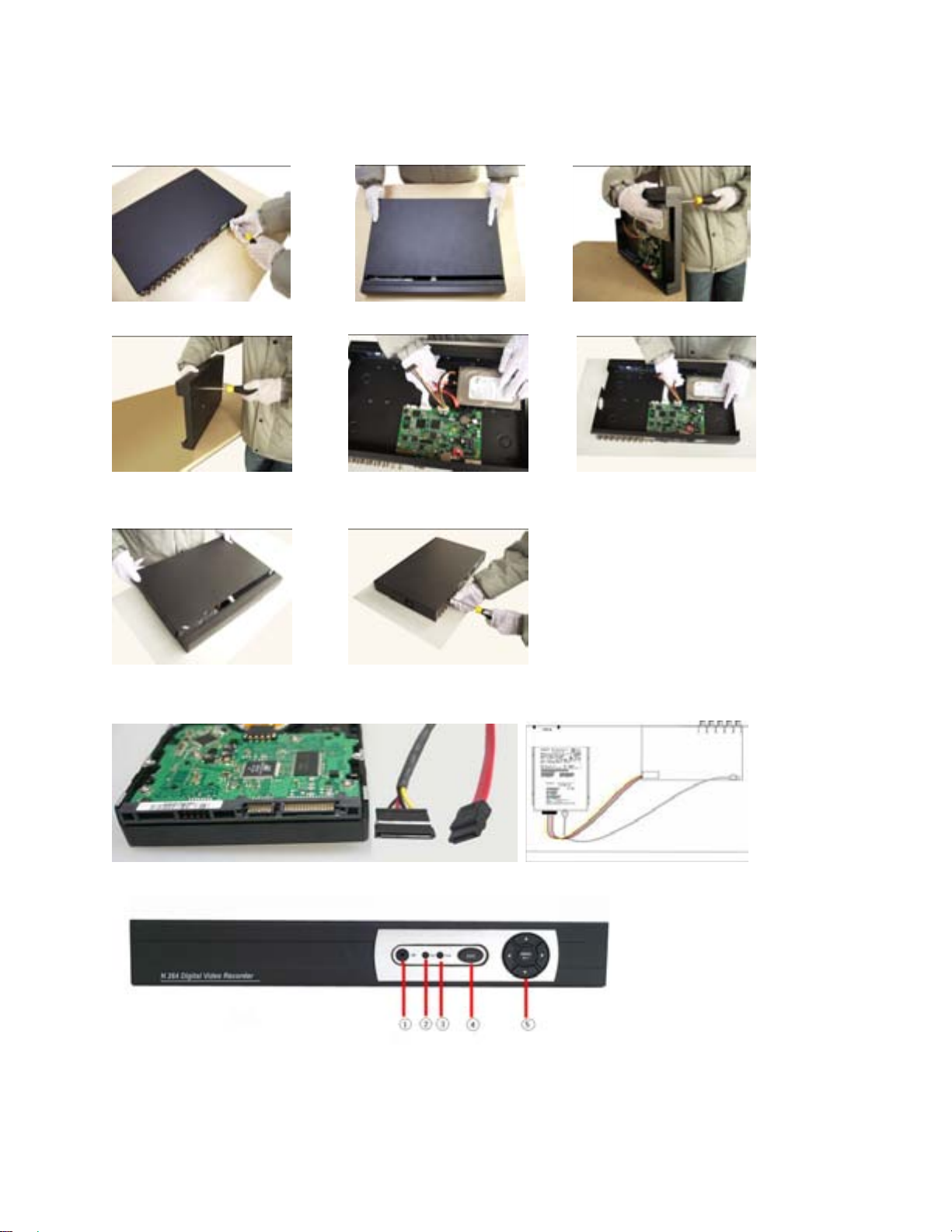
1.3 Hard disk installation
Before the first use,please install the hard disk.
Before you can record onto your HDD it should be formatted by the DVR system,
because standard PC formatting is not compatible. The format process can take several
minutes.
Your HDD should be installed inside the DVR. Please connect the(Hard Disk (HDD) in the following
way. Screw the HDD into the HDD brackets or DVR base. All necessary cables are included in the
package with the DVR. Use the instructions that came with the hard drive for exact wiring and

4
installation. Please connect the power cable to the appropriate socket, and the data cables to their
corresponding connectors.
1. Loosen the cover screw 2. Remove the cover 3. Insert the hard disk
4. Tighten the hard disk screw 5.Connect the data wire 6.Connect the power wire
7. Cover the machine 8. Tighten the cover screw
1.4 Front panel
(1) IR remote receiver (2) Record indicator light (3) Power indicator light (4) ESC (5) Left / Up / Down / Right / Menu/ Enter

5
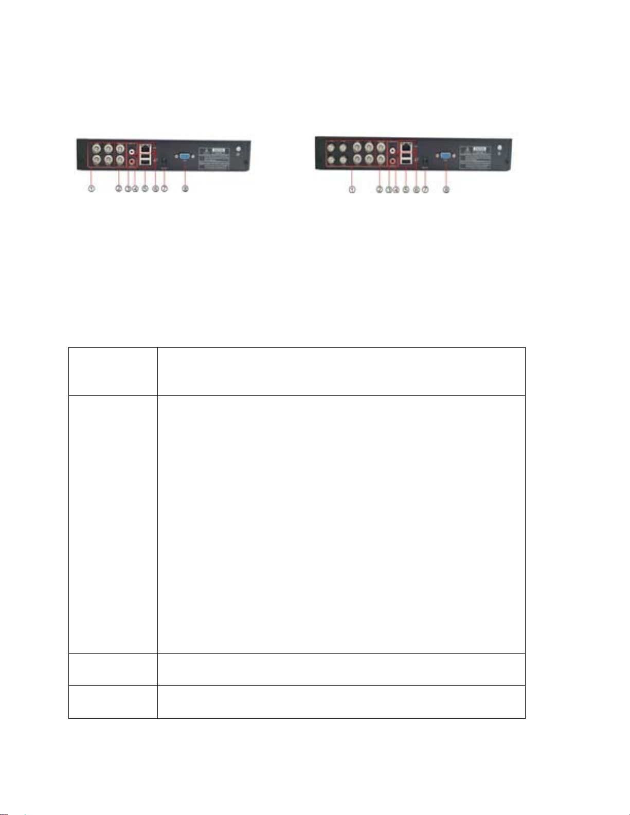
1.5 Rear panel
4CH 8CH
(1) Video inputs (2) BNC outputs (3) Audio input (4) Audio output (5) USB (6) Network
(7) Power supply (8) VGA output (9) Power Switch (ES00M140, ES00M180 without this switch)
1.6 Mouse Control
You can use a mouse to operate the DVR as well. The mouse operates just like a mouse on a
Windows PC. Please connect the mouse tone of the USB connectors (#5) in the back panel and
please note that you can hot-plug the mouse.
Right clicking
In live display mode, right clicking will either display or hide the tool bar.
In main menu or sub menu mode, right clicking will exit current menu.
Note: the settings will not be saved after right clicking.
Left clicking
When in menu unlock mode in the tool bar left click on the SYSTEM
SETTINGS icon to enter into the main menu.
After entering the main menu, left clicking will enter sub menus.
On [detail files] menu mode, left clicking will playback one recording file.
By left clicking you can select values in edit boxes or pull-down menus The
system supports Chinese character inputs, special symbols, numbers and
letters.
On the playback interface left clicking can control the >> forward function, <<
reverse function, >> I Slow play function, I > frame play function, > Play
function, and X exit function.
You can left click to adjust color control bar, volume control bar and screen
control bar.
On the main menu, sub menu or playback view, you can left click “x” to exit the
current menu.
You can left click to change the status box of a check box in the motion
detection area.
Double clicking
left key On the live view or playback video, double-clicking will maximize the screen.
Double clicking on the maximized screen will return it to the multi camera view.
Mouse drag In the Motion Detection setting interface, you can left click to drag
Mouse, and drag the frame to set the motion detection area.

6
Use the mouse to select menu items.
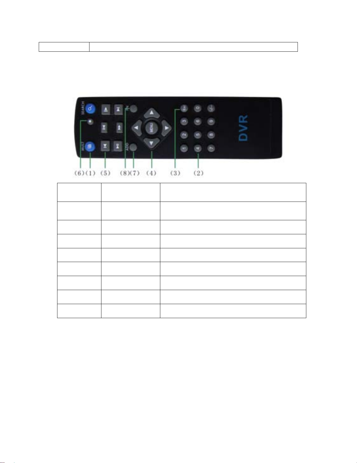
1.7 Remote controller operation
Serial
number Name Function
1 Multi-window
button Same function as Multi-window button in the front
panel
2 Numeric button Code input/number input/channel switch
3 【Esc】Same function as【Esc】button in the front panel
4 Direction button Same function as direction button in the front panel
5 Record control Control the record
6 Record mode Same function as “Record mode”
7 ADD Input the number of DVR to control it
8 FN Assistant function
1.8 Audio and Video Input/Output connections
1.8.1 Video input connections
The video input port is BNC connector plug. The demand of input signal is PAL/NTSC
BNC(1.0VP-P,75Ω).
The video signal must be accorded with the state standard which has the high signal to noise

7
ratio, low aberration and low interference. The image must be clear and has natural color in the
appropriate brightness.
Make sure the video signal stable and in good condition
The video should be installed in the appropriate location where is away from backlighting and low
illumination or adopts the better backlighting and low illumination compensation.
The ground and power supply of the video and the DVR should be shared and stable.
Make sure the transmission line stable and in good condition
The video transmission line should adopt high quality coaxial pair which is chosen by the
transmission distance. If the transmission distance is too far, it should adopt shielded twisted pair,
video compensation equipment and transmit by fiber to insure the signal quality.
The video signal line should be away from the electro magnetic Interference and other
equipments signal lines. The high voltage current should be avoided especially.
Make sure the connection stable and in good condition
The signal and shield lines should be firm and connected in good condition which avoid false and
joint welding and oxidation.
1.8.2 Video output connections and options
The video output is divided into PAL/NTSC BNC(1.0VP-P,75Ω) and VGA output(selective
configuration).
When replace the monitor by the computer display, there are some issues to notice.
1, Do not stay in the turn-on state for a long time.
2, Keep the computer display normal working by demagnetizing regularly.
3, Stay away from the electro-magnetic Interference.
TV is not a good replacement as a video output. It demands reducing the use time and control
the power supply and the interference introduced by the nearby equipments strictly. The creepage of
low quality TV can lead to the damage of other equipments.
1.8.3 Audio signal input
Audio port is RCA connection.
The input impedance is high so the tone arm must be active.
The audio signal line should be firm and away from the electro magnetic Interference and
connected in good condition which avoid false and joint welding and oxidation. The high voltage
current should be avoided especially.
1.8.4 Audio signal output
Commonly the output parameter of DVR audio signal is greater than 200mv 1KΩ(BNC) which

8
can connect the low impedance earphone and active sound box or other audio output equipments
through power amplifier. If the sound box and the tone arm can not be isolated, howling
phenomena is often existed. There are some methods to deal with the above phenomena.
1. Adopt better directional tone arm.
2. Adjust the sound box volume to be under the threshold that produces the howling
phenomena.
3. Use fitment materials that absorb the sound to reduce reflection of the sound.
4. Adjust the layout of the sound box and the tone arm.
1.9 Technical parameters
Type 4ch 8ch 16ch
System
Main processor High performance embedded microprocessor
Operation system Embedded LINUX operation system
System resource synchronous multi-channel recording, synchronous multi-channel
sub-code stream, synchronous multi-channel playback, synchronous
network operation
Interface Operation interface 16 bit true color graphical menu interface, mouse operation supportive
display ¼ image display 1/4/8/9 image display 1/4/8/9/16 image display
Video
Video standard PAL 625line,50 f/s; NTSC 525 line,60 f/s
Surveillance image
quality PAL, D1(704x576);NTSC, D1(704x480)
Playback image
quality PAL,D1(704×576);NTSC, D1(704*480)
Video compression H.264 mp
Video control 6 options
Recording speed 100/120fps (D1) 200/240fps (CIF),
50/60fps D1
400/480fps CIF
Motion detect 192(12×16) detection areas, multiple sensitivity
Audio Audio compression G711A
Bi directional Talk Support
Record
And
Recording mode manual > alarm > motion detect > timing
Playback Any channels playback, multiple channels playback

9
Playback Search mode Time searching, calendar searching, affair searching, channel searching,
information searching
Storage
And
backup
Space Occupation Audio: 28.8MB/H Video:25~450MB/H
Recording storage Hard disk, network
Backup mode Network, USB flash Drive
Port
Video input 4 BNC 8 BNC 16 BNC
Video output 2 BNC, 1 VGA
Audio input 1 RCA 1 RCA
Audio output 1 RCA
Network port RJ45 10M/100M
USB port 2* USB2.0 ports
Hard disk port 1 SATA port
Other
Power supply 12V/2A external power supply
Power consumption <15W (without hard disk)
Working temperature 0°~ + 55°C
Working humidity 10%-90%
Air pressure 86kpa-106kpa
Size 260*200*43mm
Weight 2kg(without hard disk)
Installation Desktop
.

10
Getting Started and Main Menu
2. Basic operation
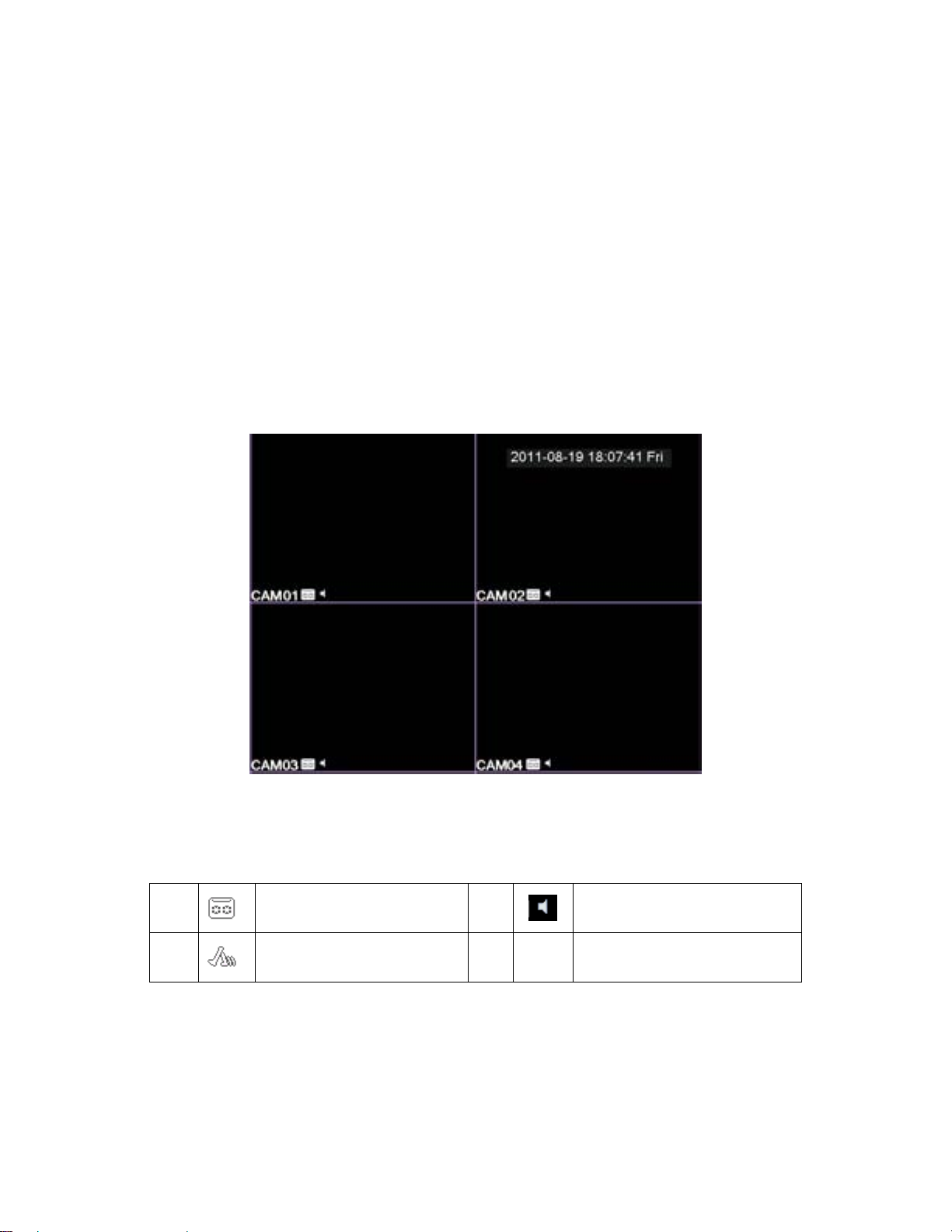
2.1 Preview
Note: The button in gray display indicates nonsupport.
You can right click mouse to choose the switch between the windows.
The system date, time and channel name are shown in each viewing window. The surveillance video
and the alarm status are shown in each window.
1 Recording status 3 Audio
2 Motion detect 4 ? No Video
Table of Preview: icon
Autres manuels pour ES00M140
1
Ce manuel convient aux modèles suivants
1
Table des matières
Autres manuels eSecure DVR