Envirovent heatSava Manuel utilisateur
September 2014
Please read these
instructions

SHOULD YOU ENCOUNTER ANY PROBLEMS INSTALLING THIS UNIT CALL
Contents
Page
01 Introduction 1
02 Technical Specications 2-3
03 Wiring Diagrams 4-5
04 Safety 6-7
05 Box Contents 8-9
06 Tools Checklist 10
06A Pre-Installation Checklist 11
07 Controls 11
08 Pre-Installation 12-13
09 Installation 14-26
Installation with wall seal 17-18
Installation with wall sleeve 19
10 Cleaning & Maintenance 27-29
11 Guarantee 30
12 Warranty 30
01
Gold Standard After Sales Service
In the unlikely event of any on-site installation problems or queries regarding the EnviroVent heatSava, just call our hotline
number. We will take your details and appoint a regional installation manager to call you back to discuss the problem. In the
majority of cases, the problem can be resolved over the phone. However, in cases where the problem cannot be resolved
over the phone, we will arrange a visit from our Gold Standard Engineer. They will meet with your contractor/direct labour
on-site to discuss and resolve the problem, will provide training and also give advice on the installation of the unit.
INSTALLER HOTLINE: 07540 050 147
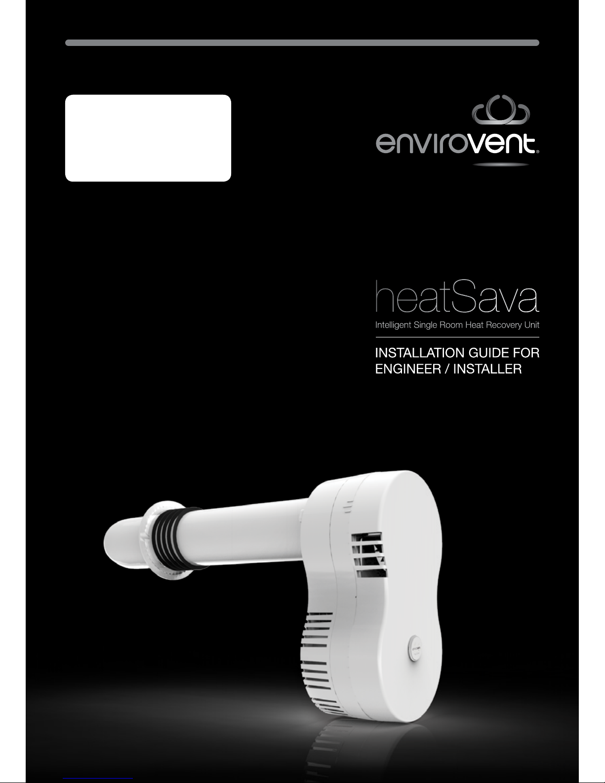
01 Introduction
Thank you for choosing EnviroVent
The fastest growing ventilation company in the UK
Ensure that this product is treated with care, installed and maintained correctly i.e. for
the life of the building. Remember, if you have any problems please call our dedicated
Technical Team.

AFTER INSTALLING THIS UNIT PLEASE PASS ONTO END USER
DO NOT THROW AWAY
02
02 Technical Specications
Unit Dimensions
Cowl End
Heat Cell
Fan Adaptor
Assembly
(Supply Fan)
Centre Assembly
(Electronics)
Front Cover
Rear Assembly
(Extract Fan)

SHOULD YOU ENCOUNTER ANY PROBLEMS INSTALLING THIS UNIT CALL
02 Technical Specications
Heat Cells Options
Ø100
Ø150
03
Wall Depth mm
(A)
Cell Order Size mm
(B)
100 - 330 330
331 - 430 430
431 - 500 500
501 - 600 600

AFTER INSTALLING THIS UNIT PLEASE PASS ONTO END USER
DO NOT THROW AWAY
04
03 Wiring Diagrams
Mains - This unit must be earthed
Connect 2 core & earth
cable into existing wiring

SHOULD YOU ENCOUNTER ANY PROBLEMS INSTALLING THIS UNIT CALL
05
03 Wiring Diagrams
SELV - This unit must be earthed
Connect 2
core cable
from SELV
box into unit
Connect 2
core & earth
cable to
existing wiring
2 core & earth2 core
SELV
2 core 2 core
& earth
SELV Box must be
secured using the 4
xing points
Cables must be
restrained inside
SELV box
SELV Box
Power Supply
GND
V+
GND V+

AFTER INSTALLING THIS UNIT PLEASE PASS ONTO END USER
DO NOT THROW AWAY
06
04 Safety
• Never modify the fan or electronics.
• Do not store inammable products in the
vicinity of this product.
• This appliance can be used by children
aged from 8 years and above and
persons with reduced physical, sensory or
mental capabilities or lack of experience
and knowledge if they have been given
supervision or instruction concerning
use of the appliance in a safe way and
understand the hazards involved. Children
shall not play with the appliance. Cleaning
and user maintenance shall not be made
by children without supervision.
• For a bathroom application the power
supply should be installed outside the
bathroom as it is 230V.
Be sure to have read and understood these
instructions before beginning the installation
process.
IPX4 Rated
This unit has been tested to IPX4 and is
suitable for installation within Zone 1 of
bathrooms. However, we recommend
that you must not position the unit
above any water devices such as taps,
shower heads or jets and ensure water
is not aimed directly at the unit. Do not
use jets or shower heads etc to clean
this unit.
All wiring must comply with Building
Regulations and the current I.E.E. Wiring
Regulations (BS7671) or the equivalent
standards for your country. The nal
installation should be examined and
tested by a qualied electrician.
Make sure the mains supply complies
with the rating label for voltage,
frequency and phase.
IMPORTANT: This unit draws air in
from atmosphere and you must ensure
that any emissions from any other
systems such as gas or oil boilers, do
not contaminate the air entering the
heatSava product. Therefore, before
installation, consider where the external
cowl will be located in relation to any
boiler ues etc. Externally, you must
ensure that the unit is positioned a
minimum distance away of; 1 metre
horizontally, 1 metre below or 3 metres
above any boiler ue etc.
In kitchens, if the unit has to be tted
above a cooker, it must be installed a
minimum distance of 650mm above
electric cookers and 750mm above gas
cookers, and not have a pullcord tted.

SHOULD YOU ENCOUNTER ANY PROBLEMS INSTALLING THIS UNIT CALL
07
04 Safety
Electrical Assembly
When wiring the unit in, a suitable
disconnect device such as a fused spur
should be used, do not use a plug. The
means of disconnecting the unit from the
mains power supply must be incorporated
in the xed wiring in accordance with the
wiring rules.
There must be a necessity to allow
disconnection of the appliance from the
supply after installation, unless the appliance
incorporates a switch complying with the
wiring regulations The disconnection may
be achieved by incorporating a switch in the
xed wiring in accordance with the wiring
regulations.
The electrical install comprises of a power
supply unit (Fig.1) or a low voltage box
- SELV (Fig.2). See pages 4-5 for wiring
diagrams.
If the supply cord is damaged, it must be
replaced by the manufacturer, its service
agent or similarly qualied persons in
order to avoid a hazard.
SELV Box
MAINS
Fig.1
Fig.2
Fan
Board
Power
Supply
Connect 2 core
& earth cable into
existing wiring
Connect 2
core cable
from SELV
box into unit
Connect
2 core
& earth
cable to
existing
wiring
2 core
& earth2 core
SELV
Cables must be
restrained inside
SELV box.

AFTER INSTALLING THIS UNIT PLEASE PASS ONTO END USER
DO NOT THROW AWAY
05 Box Contents
1 heatSava Unit
2 Heat Cell
3 Instructions Guide
4 SELV (optional)
5 Halo
6 Wall Seal
7 Fixing Template
8 Fixing Kit
08

SHOULD YOU ENCOUNTER ANY PROBLEMS INSTALLING THIS UNIT CALL
09
05 Box Contents
Description Quantity Item
heatSava Unit 1x
Heat Cell 1x
Instructions Guide 1x
SELV (optional) 1x
Halo
(Wall Kit Contents) 1x
Wall Seal 1x
Fixing Template 1x
Fixing Kit 1x
8G X 2.0” -
(Fixing Kit Contents) 6x
Red Wall Plugs -
(Fixing Kit Contents) 6x
Terminal Block
(Spare) 1x
Autres manuels pour heatSava
4
Table des matières
Manuels Chauffage populaires d'autres marques

oventrop
oventrop Regucor Series Manuel utilisateur

Blaze King
Blaze King CLARITY CL2118.IPI.1 Manuel utilisateur

ELMEKO
ELMEKO ML 150 Manuel utilisateur

BN Thermic
BN Thermic 830T Manuel utilisateur

KING
KING K Series Mode d’emploi

Empire Comfort Systems
Empire Comfort Systems RH-50-5 Guide de démarrage rapide


Empire Heating Systems
Empire Heating Systems WCC65 Manuel utilisateur

Wetekom
Wetekom 92 86 43 Manuel utilisateur

Desa
Desa SPC170-F Manuel utilisateur

Watlow
Watlow Watrod Electric Tubular Heaters Manuel utilisateur

Haverland
Haverland ECO-DRY GPS Series Manuel de la liste des pièces

Stelpro
Stelpro ASILVC2060 Series Manuel utilisateur