
Enkeeo SC2300i Manuel utilisateur

SC2300i Inverter Generator
User Manual

CONTENTS
Safety Instructions·····················································1
Controls and Features··············································2
Getting Started··························································4
Electrical Connection················································6
Maintenance·····························································9
Storage ···································································12
Troubleshooting and Specifications·······················13
Warranty ·································································14
Contact Us ·····························································14

Thanks for choosing ENKEEO. This manual contains important information, for your safety and perfect
experience, please read this manual carefully, and keep it for future reference.
Safety Instructions
WARNING! Read and understand all safety precautions in this manual before operating. Failure to
comply with instructions in this manual could result in personal injury and/or property damage.
FUEL IS HIGHLY FLAMMABLE AND POISONOUS
• Always turn off the engine when refueling.
• Never refuel while smoking or in the vicinity of an open flame.
• Take care not to spill any fuel on the engine or muffler when refueling.
• If you swallow any fuel, inhale fuel vapor, or allow any to get in your eye(s), see your doctor immediately.
If any fuel spills on your skin or clothing, immediately wash with soap and water and change your clothes.
• When operating or transporting the machine, be sure it is kept upright. If it tilts, fuel may leak from car-
buretor or fuel tank.
EXHAUST FUMES ARE POISONOUS
• Never operate this product in a closed area or it may cause unconsciousness and death within a short
time. Always operate this product in a well ventilated outdoor area.
ENGINE AND MUFFLER MAY BE HOT
• When operate the generator, place it in a safe area away from pedestrians or children.
• Avoid placing any flammable materials near the exhaust outlet during operation.
• Keep the generator at least 1m(3 ft) from buildings or other equipment, or the product may overheat.
• Do not operate the product with a dust cover, or other objects covering it.
• When covering the generator, be sure to do so only after the engine and muffler have completely cooled down.
• Be sure to carry the generator only by its carrying handles.
• Do not place any obstacles on the generator.
TO PREVENT ELECTRIC SHOCK
• Never operate the product in rain or snow.
• Never touch the generator with wet hands or electrical shock can occur.
GROUNDING
• Properly ground generator to prevent electric shock.
• Connect the ground terminal of the generator to the ground electrode buried in the ground.
WARNING NOTES
• Failure to properly ground the generator can result in electric shock.
• Be sure to always comply with electric loads.
CONNECTION
• Before the generator can be connected to a building’s electrical system, a license electrician must in-
stall an isolation (transfer) switch in the building’s main fuse box. The switch is the connection point for
generator power and allows selection of generator or main line power to the building. This will prevent
the generator from charging the main power line (back feeding) when the main power supply has failed
or has been turned off for line maintenance. Also, generator and building electrical system damage can
occur when normal operating power returns if unit is used without an auto-switch.
• Always use proper approved electrical cords. Be sure to comply with all electric codes.
• Do not use electrical cords that are worn or damaged.
• Always use GFCI (ground fault circuit interruptor) for damp locations.
EN-1
• Always use proper approved transfer switch to isolated generator from the electric panel.
Controls and Features
Generator
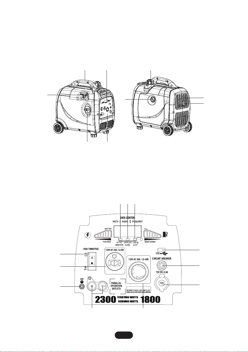
1. Muffler
2. Carrying Handle
3. Vented Gas Cap
4. Recoil Starter
5. Control Panel
Control Panel
1
7
8
36
59
4
2
4
1
11
9
7 10
6
5
8
3 2
EN-2
6. Fuel Gauge
7. Exhaust and Spark Arrester
8. Oil Filler Cap
9. Multi-Switch
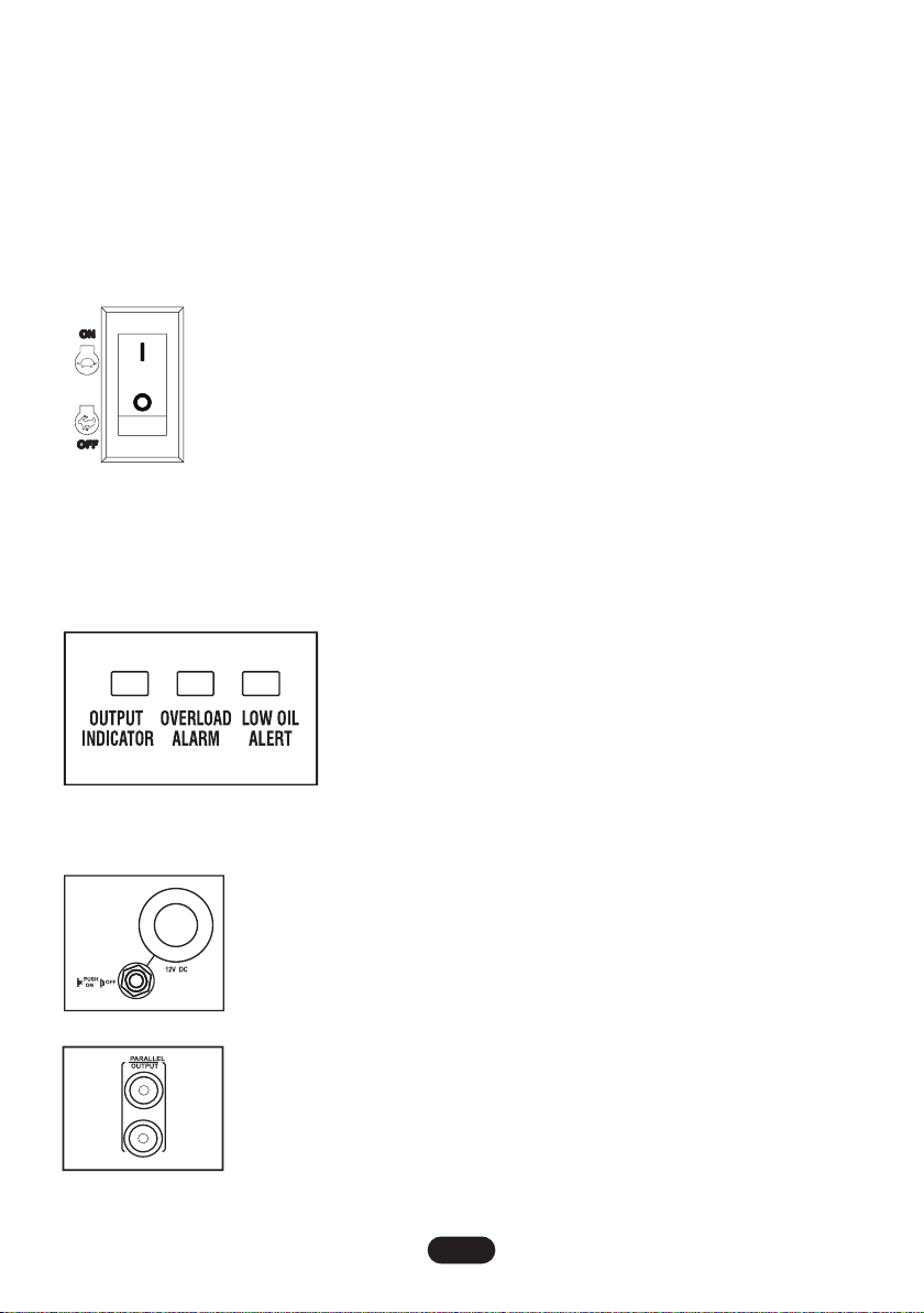
1. Economy Throttle
2. Low Oil Alarm
3. Overload Alarm
4. Output Indicator
5. DC Circuit Breaker
6. 12V DC Output
Control Functions
1. ECO THROTTLE
When the Throttle switch is in the “ON” position, the throttle controls the engine speed
according to the connected electrical load. The results are better fuel consumption and
less noise. When the switch is in the “OFF” position, the engine runs at 4,500 rpm re-
gardless of the electrical load.
Note: The Throttle must be “OFF” when using electrical devices that require a large
starting current, such as a compressor, pump, or refrigerator.
2. LED Indicators
The LED Indicators assist in communicating status and functions of the unit.
Output Indicator (Green)
The Output Indicator comes on when the engine starts and produces power.
Overload Alarm (Red)
The Overload Alarm comes on when a connected device requires
more power than the generator is able to produce. The Output Indica-
tor will go off and the Overload Alarm will stay on, but the engine will
continue to run.
Low Oil Alert (Red)
When the engine oil falls below the required level, the Low Oil Alert will
come on and the engine will stop automatically. The engine will not restart until oil is added to bring it up
to the appropriate level.
3.12V 8A DC
The 12V 8A DC Output is provided for battery charging. Follow instructions in the
owner’s manual for the battery charging procedures.
4. 8A DC Circuit Breaker
The 8A DC Circuit Breaker turns off automatically if the current exceeds 8A. If the
circuit breaker turns “OFF”, you will need to push it to turn it “ON” again.
5. Parallel Output
Two generators can be connected to increase output. Put parallel wire into the
socket first, then start the two greater wattage as the normal process.
Note: Put the connection wire into the right sockets.
EN-3
7. Parallel Output
8. 5V 1A DC USB
9. Ground Terminal
10. 120V L5-30R
11. 120V 5-20R
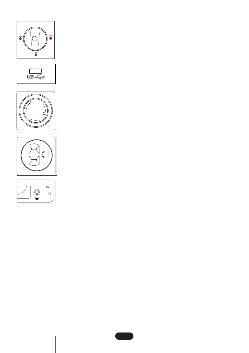
6.Multi-Switch
The Multi-Switch control fuel valve, choke and engine switch.
When starting the generator, rotate the Multi-Switch counter clockwise from STOP to
START position, then pull recoil cord quickly to start. After started, rotate the switch to
RUN position.
Note: To shut off generator, rotate Multi-Switch clockwise to STOP position and hold
until generator turns off.
7. 5V 1A DC USB
8.120V AC Outlet
The Outlet is used to power 120V Single Phase 60Hz requiring up to 1600W continu-
ous power.
120V AC twist lock receptacle (NAME LR-30R) may be used to supply electrical power
when parallel connection.
Note: When two generators are connected in parallel for greater wattage loads, an
RV (NAME TT-30) adaptor is provided.
9. 120V 5-20R
The Outlet is used to power 120V Single Phase 60Hz loads requiring up to 1600W
continuous power.
10.Ground Terminal
Properly ground generator to prevent electrical shock.
Connect the ground terminal of generator to ground electrode buried in the ground.
Getting Started
Unpack the generator
Remove the generator from its packaging.
WARNING! Packaging is flammable! Do not attempt to add fuel to this unit before removing it from
packaging.
Inspect the generator to ensure that no damage has occurred in shipping or handling. If the unit appears
to be damaged, do not add fuel or attempt to start the generator.
Check to ensure that you received the following items:
• Generator
• 12V Charging Cables
• Parallel Output Wire
• Oil Funnel
• Engine Oil (400ml)
• RV Adaptor
EN-4
Adding engine oil
The generator has been shipped with engine oil.
Do not add fuel or start the engine before adding engine oil.
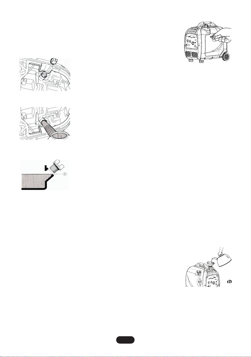
In order to add motor oil, you will need to remove the side panel from the
unit (figure 1).
Place the generator on a level surface.
Do not tilt the generator while adding oil. It can cause you to overfill the
oil and/or cause the oil to leak into areas in which it is not intended.
Remove the oil filler cap (figure 2).
Using the funnel (provided) fill with 0.42 quart SAE 10W-30 or 10W-40 (figure 3).
See figure 4 for proper oil level.
Replace oil filler cap and secure side panel with screws.
Recommended engine oil:
YAMALUBE 4 (10W-40)
SAE 10W-30 or 10W-40
SAE #30
SAE #20
SAE #10W
Recommended engine oil grade: API Service SE type or higher
Engine oil quantity: 0.4L (0.42 US qt)
Adding fuel
Do not overfill the tank, otherwise it may overflow when the fuel warms up and expands.
1. Use clean, fresh, regular unleaded fuel with a minimum octane rating of 85.
2. Do not mix oil with fuel.
3. Clean area around the fuel cap.
4. Remove the fuel cap.
5. Be sure that the fuel strainer is in place.
6. Slowly add fuel to the tank.
7. Do not exceed the red marker position of the fuel filter.
8. Screw on the fuel cap and wipe away spilled fuel.
Note: Use only unleaded gasoline. The use of leaded gasoline will cause se-
vere damage to internal engine parts.
After filling with fuel, make sure the fuel tank cap is tightened securely.
Starting the engine
Operate the engine in a well ventilated area.
Do not connect any electrical devices to the outlets on the generator before starting the engine.
(figure 1)
(figure 4)
(figure 2)
(figure 3)
EN-5
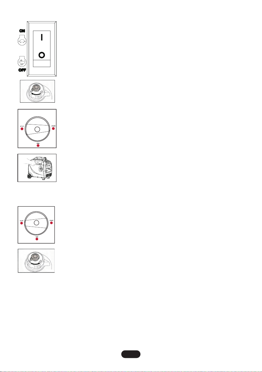
1.Turn the Economy Throttle switch “OFF”. You may turn the Economy Throttle switch
to “ON” once the engine is started and a steady idle is achieved.
2.While holding the fuel tank cap so that it will not move, turn the air vent knob to “ON”
position.
3. Turn the Multi-Switch to “START” position.
4. Grasp the carrying handle firmly to prevent the generator from falling over when
pulling the recoil starter.
5. Pull slowly on the recoil starter until it is engaged and then pull it briskly.
6. After the engine starts, warm up the engine until the engine does not stop when the
choke knob is returned the run position.
Stopping the engine
Before stopping the engine, turn off and disconnect any electronic devices attached to the generator.
1. Turn the Multi-Switch to the “STOP” position.
2. While holding the fuel tank cap so that it will not move, turn the air knob to “OFF” po-
sition.
Electrical Connection
Capacity
Follow these simple steps to calculate the running and starting watts necessary for your purposes.
1.Select the electrical devices you plan on running at the same time.
2.Total the running watts of these items. This is the amount of power you need to keep your items running.
3.Identify the highest starting wattage of all devices identified in step 1.
Power management
Use the following formula to convert voltage and amperage to watts: Volts x Amps = Watts
To prolong the life of your generator and attached devices, follow these steps to add electrical load:
EN-6
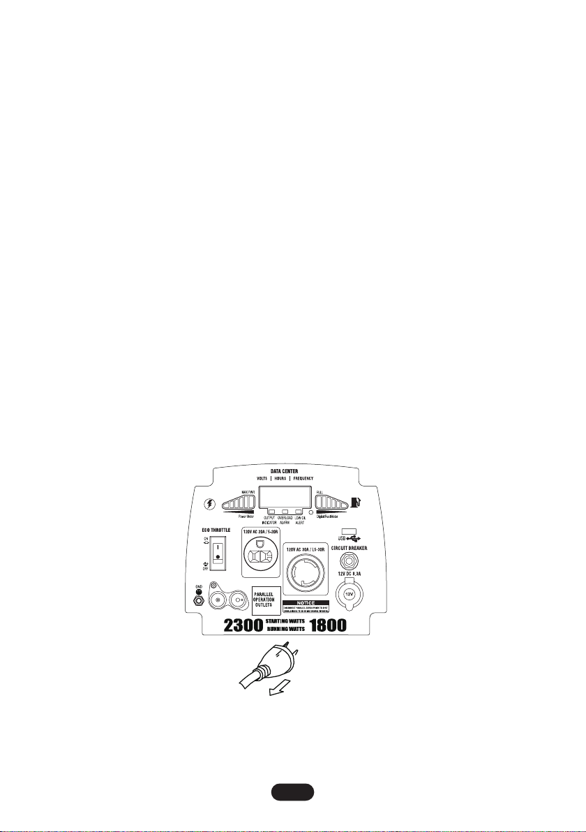
1. Start the generator with no electrical load attached.
2. Allow the engine to run for several minutes to stabilize.
3. Plug in and turn on the first item. It is best to attach the item with the largest load first.
4. Allow the engine to stabilize.
5. Plug in and turn on the next item.
6. Allow the engine to stabilize.
7. Repeat steps 5 to 6 for each addition.
Connecting electrical loads
1. Let the engine stabilize and warm up a few minutes after starting.
2. Prior to power tools and equipment, make sure the generator’s rated voltage, and amperage (120V AC
at 7 AMP, 12V DC at 8 AMP) is adequate to supply all electrical loads that the unit will power. If powering
exceeds the generator’s capacity, it may be necessary to group one or more of the tools and/or equip-
ment for connection to a separate generator.
3. Once the generator is running, simply connect the power cords of 120V AC powered tools and equip-
ment into the 120V AC dual outlets and/or the power cord of a 12V DC powered tool to the DC terminals.
4. Do not connect 3-phased loads to the generator.
5. Do not connect 50Hz loads to the generator.
6. Do not overload the generator.
Note: The DC terminal may be used for charging 12V automotive type batteries only.
Parallel connection within 2 generators
Performance: Allows you to increase the output by connecting two generators together. By using the par-
allel connection wires provided.
Instant increased power once connected: Parallel running watts = 3420 watts / 28 AMP
Attention: Be sure that generators are powered off and without load when connecting the parallel wires.
1. Put the parallel connection wire 1 and 2 into the parallel connection sockets 3 and 4.
Attention: Grounding wire must be properly connected.
EN-7
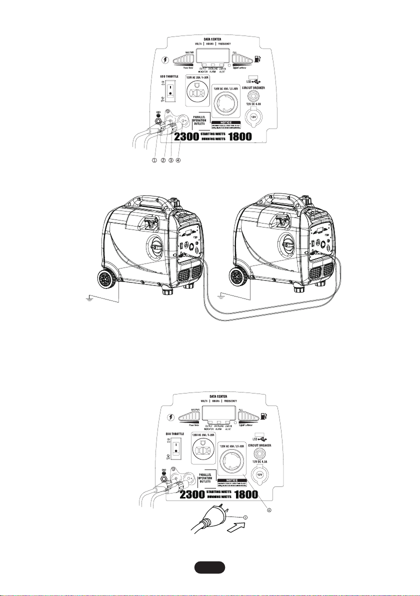
2. Start 2 sets of inverter generators. The starting operation is as the same as normal process (refer on
manual book starting parts).
Attention: Please make sure the parallel connection wires have been put into the parallel connection
sockets properly. If not connected properly, inverter generator could be damaged.
3. The load plugs can now be plugged into socket 6.
EN-8
Table des matières


