Enertech Bentone ST 133 K Caractéristiques techniques

Providing sustainable energy solutions worldwide
178 004 17-1 2016-04-26
Installation- and maintenance instruction
ST 133 K


DESCRIPTION
1. Reset button
2. Control box
3. Ignition transformer
4. Ignition cables
5. Nozzle assembly
6. Nozzle
7. Brake plate
8. Blast tube
9. Ignition electrodes
10. Connecting pipe
11. Air damper
12. Solenoid valve
13. Pump
14. Drive coupling
15. Indication, air damper
16. Fan wheel
17. Adjustment, air damper
18. Photoresistor
19. Motor
171 205 32 07-01
Components
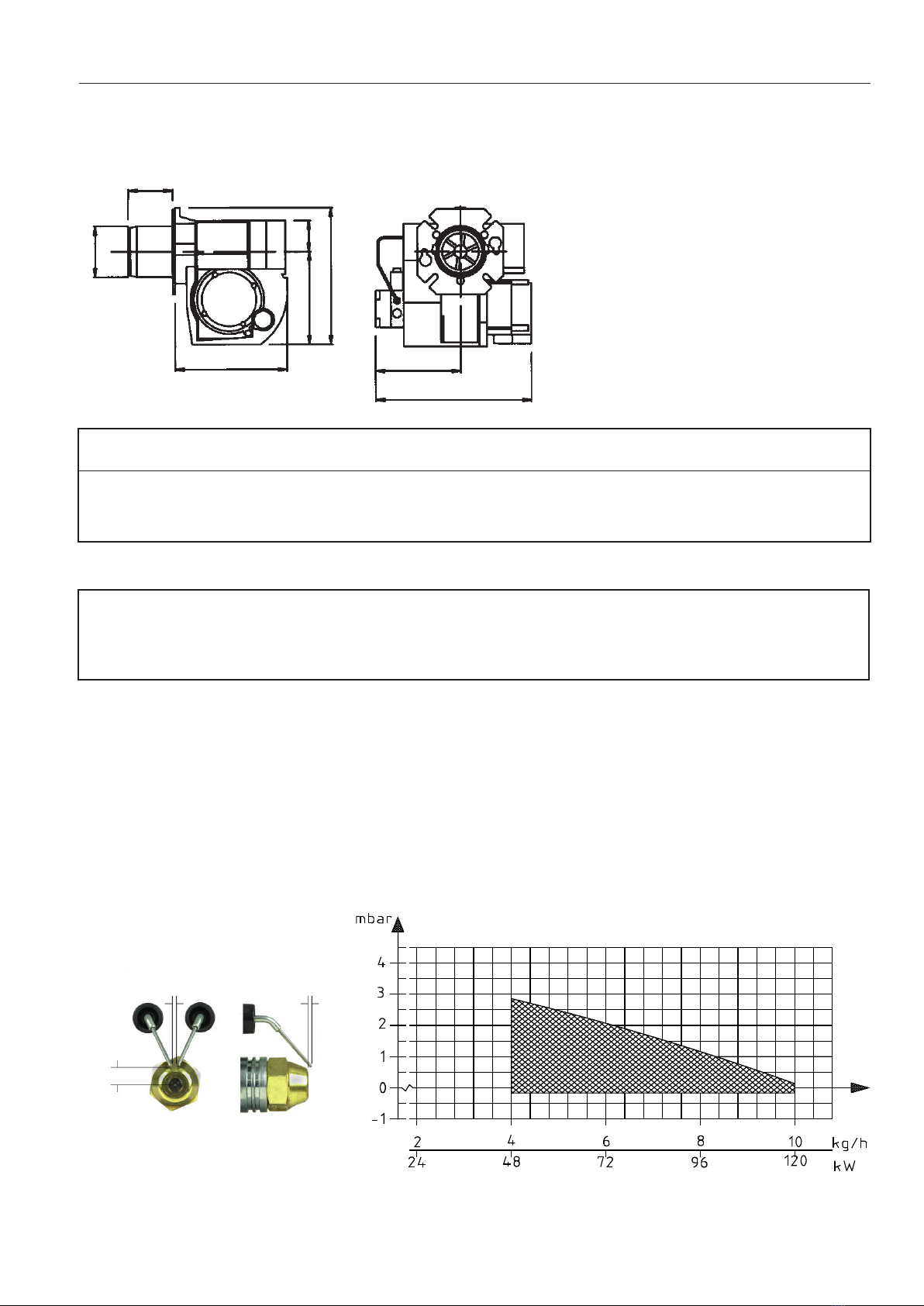
Dimensions
2,3-3,1 0,5-1,5
10,0-11,0
171 225 38 07-01
TECHNICAL DATA
Electrode adjustment
Because of dierent boiler types
existing on the market, with varying
combustion chamber designs, it is
not possible to state a denite spray
angle or spray pattern.
Recommended nozzle
Note that the spray angle and the
spray pattern change with the pump
pressure.
Output range and nozzles recommended
The net caloric value of 11,86 kWh/kg for light oil has been used.
Burner tube Length of burner
tube
Incl. ange A
Measure B
Incl. ange B
Measure B
Incl. ange C
Measure B
Incl. ange D
Measure B
K 94 59 72 80 79
K 147 112 125 133 132
K 224 189 202 210 209
Burner tube Oil capacity Capacity Recommended
Nozzle
Recommended Pump
pressure
kg/h kW Mcal/h Angle Type Bar
K 4,0-10,0 47-119 41-102 45°, 60° B, S 10
B
158
ø89
54
200
258
237
295
Type designation ST133K

TECHNICAL DATA
171 215 76 07-01
Flange A
10,3
25
130-150
ø89,7
Flange C
10
125
ø90 4
Flange D
125-150
10,3
ø90 5
12
Flange B
ø89,5 12
136-150
Dimensions

General rules
The installation of an oil burner should
be carried out in accordance with local
regulations. The installer of the burner
must therefore be aware of all regula-
tions relating to oil and combustion.
Only oil suitable for the burner should
be used and then in combination with
a suitable oil lter before the oil pump
of the burner.
If the burner is replacing an existing
burner make sure that the oil lter is
replaced or cleaned. The installation
must only be undertaken by expe-
rienced personnel. Care should be
taken by the installer to ensure that no
electrical cables or fuel/gas pipes are
trapped or damaged during installation
or service/maintenance.
Installation instructions
General installation instructions ac-
company the burner and should be
left in a prominent place adjacent to
the burner.
Adjustment of burner
The burner is from the factory pre-set
to an average value that must then be
adjusted to the boiler in question.
All burner adjustments must be made
in accordance with boiler manufactu-
rers instructions.These must include
the checking of ue gas temperatures,
average water temperature and CO2
or O2concentration.
To adjust the combustion device,
start by increasing the air volume
somewhat.
When the burner starts it is burning
with excess air and smoke number
0. Reduce the air volume until soot
occurs and increase again to reach
a combustion free of soot.
By this procedure an optimum adjust-
ment is obtained. If larger nozzles
are used the preadjustment of the air
volume must be increased.
Condensation in chimney
A modern burner works with less
excess air and often also with smal-
ler nozzles than older models. This
increases the eciency but also the
risk of condensation in the chimney.
The risk increases if the area of the
chimney ue is too large. The tempe-
rature of the ue gases should exceed
60°C measured 0,5 metres from the
chimney top.
Pump adjustment
See separate description.
Adjustment of burner
To obtain a correct adjustment a
ue gas analysis and a temperature
measurement must be carried out.
Otherwise there is a risk that a bad
adjustment may cause a formation of
soot, bad eciency or condensate in
the chimney.
Maintenance
The boiler/burner should be examined
regularly for any signs of malfunction
or oil leakage.
GENERAL INSTRUCTIONS
Measures to raise the temperature:
Insulate the chimney in cold attics
Install a tube in the chimney
Install a draught regulator (dilutes the
ue gases during operation and dries
them up during standstill)
Increase the oil quantity
Raise the ue gas temperature by
removing turbulators, if any, in the
boiler.
Instructions for use
The end user of the burner should be
instructed about the operation and
safety features of the burner.
He should also be made aware of
the importance of the area around
the boiler/burner being kept free of
combustible material.
Air adjustment 0 - 32
171 305 69 07-01
Adjustment of nozzle assembly 0 - 22
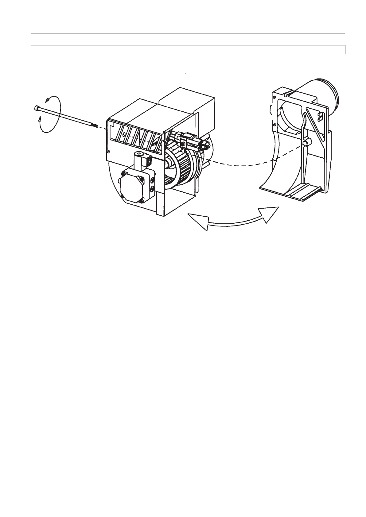
MAINTENANCE OF OIL BURNER
Warning: Before doing any service switch o power at the main switch and cut o the oil supply
171 305 68 07-01
Service of burner head and nozzle assembly

171 435 25 16-01
ELECTRIC EQUIPMENT
Oil burner control: LMO14.113... / LMO24.255...
List of components
A1 Oil burner control
A2 Twin thermostat
F1 Fuse, max. 10A
H1 Alarm lamp
H2 Signal lamp (optional)
M1 Burner motor
P1 Time meter (optional)
R1 Photoresistor
S3 Main switch
T1 Ignition transformer
Y1 Solenoid valve
X1 Plug-in contact, burner
X2 Plug-in contact, boiler
Outer electrical connection
Mains connection
and fuses in
accordance with
local regulations.
* If there is no plug-in contact (X2) on the boiler,
connect to the contact enclosed. In case the
twin thermostat is in series on incoming phase
L1, a loop between the terminals T1 and T2 is
necessary.
Wiring diagram
*
1(3)
X1
X2

171 435 25 16-01
Function
1.Switch on operating switch and twin thermostat
The burner motor starts, an ignition spark is formed, the prepurge goes
on till the prepurge period expires and the solenoid valve opens.
2. Solenoid valve opens
Oil mist is formed and ignited. The photocell indicates a ame. The ignition
spark goes out after ame indication (See Technical data oil burner control).
3. The safety time expires
a. If no ame is established before this time limit the control cuts out.
b. If for some reasons the ame disappears after this time limit, the
burner will make an attempt to re-start.
3-4. Operating position
If the burner operation is interrupted by means of the main switch or the
thermostat, a new start takes place when the conditions in accordance
with point 1 are fullled.
The oil burner control cuts out
A red lamp in the control is lit. Press the reset button and the burner
re-starts.
ELECTRIC EQUIPMENT
Technical data oil burner control
LMO14.113... LMO24.255...
Pre-ignition time: 15 s 25 s
Pre-purge time: 16 s 26 s
Post-ignition time: 3 s 5 s
Safety lock-out time: < 10 s < 5 s
Reset time after lockout: < 1 s < 1 s
Reaction time on ame failure: < 1 s < 1 s
Ambient temperature: -5 +60°C -20 - +60°C
Min. current with ame established: 45 µA 45 µA
Max. photo current at start: 5,5 µA 5,5 µA
Control of photo current
Current through photo unit is measured with a d.c. ammeter (a moving coil
instrument connected in series with the photo unit).
2(3)

171 435 25 16-01
Colour codes LMO14/24
When the burner starts, three signal lights in the reset switch indicate
the normal sequence, as well as provide indication if something ab-
normal is happening in accordance with the following table:
Preheater in operation Solid yellow
Ignition switched on Flashing yellow
Normal operation Solid green
Operation, poor ame signal Flashing green
Undervoltage Flashing yellow-red
Fault, alarm Solid red
False light Flashing red-green
Communication mode Fluttering red
Fault codes LMO14/24
When the red light for a blocked relay box comes on, you can get
information about what has caused the problem by pressing and
holding the reset button for 3 seconds.
The number of ashes below is repeated with a pause in between.
2 ashes No ame signal when safety time
expires
4 ashes False light during start
7 ashes 3 x Losses of ame during operation
8 ashes Time-out for preheater *
10 ashes Incorrect wiring, internal fault or si-
multaneous occurrence of two faults
* In order for this fault code to occur, the preheater shall not reach
its cut-o temperature within 10 mins. from switch on.
To return to normal operation: Press the reset button for 1 second.
If the reset button is instead kept pressed a second time for at least
3 seconds, you can, via an interface, obtain the corresponding in-
formation on a computer or ue gas analyser.
To return to normal operation: Press the reset button for 1 second
3(3)
Table des matières
Autres manuels Enertech Four


