2/5
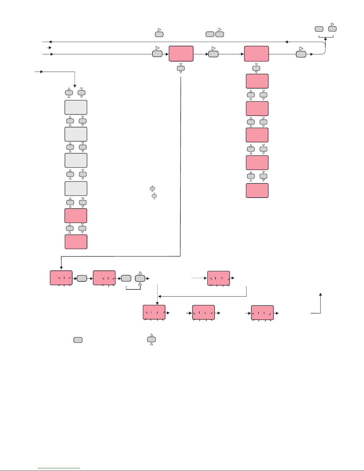
A1.tp.
IndE.
A2.tp.
IndE.
A1.St.
HI.
A2.St.
HI.
A1.P.e.
on
A1.Hy.
2
A2.Hy.
2
ALr.o. ConF.
A1.p.e. = State of Alarm1 output in the
case of sensor failure.
If A1.p.e.= On , the alarm output is
energized during the sensor failure.
If A1.p.e.= oFF, the alarm output is not
energized during the sensor failure.
A2.p.e. =
case of sensor failure.
If A2.p.e.= On, the alarm output is
energized during the sensor failure.
If A2.p.e.= oFF, the alarm output is not
energized during the sensor failure.
NOTE! If C.ot.S. = .out1, this
parameter is not seen.
State of Alarm2 output in the
A1. =
output.
Adjustable between 1 and 50°C.
Hysteresis decimal scale value can be
adjusted between 0.1°C and 5.0°C for
Hy. Hysteresis of the Alarm1
A2. =
output.
Adjustable between 1 and 50°C.
NOTE! If C.ot.S. =.out1, this
parameter is not seen.
Hy. Hysteresis of the Alarm2
A1.tP. =
Four kinds of functions can be selected.
indE. = Independent
dE. = Deviation
bAnd = Band
bAn.i. = Band with inhibition
Function of Alarm1 output.
A2.tP. =
Four kinds of functions can be selected.
indE. = Independent
dE. = Deviation
bAnd = Band
bAn.i. = Band with inhibition
NOTE! If C.ot.S. = .out1, this
parameter is not seen.
Function of Alarm2 output.
A1.St. =
If independent or deviation alarm is
selected, this parameter can be Lo.
and Hi.. For Lo. alarm output is
energized below the alarm set point. For
Hi. alarm output is energized above the
alarm set point. If band alarm is
selected, this parameter can be bIHI
or boHI. bIHI means alarm is
activated inside the band.boHI means
alarm is activated outside the band.
The state of Alarm1.
A2.St. =
If independent or deviation alarm is
selected, this parameter can be Lo.
and Hi.. For Lo. alarm output is
energized below the alarm set point. For
Hi. alarm output is energized above the
alarm set point. If band alarm is
selected, this parameter can be bIHI
or boHI. bIHI means alarm is
activated inside the band.boHI means
alarm is activated outside the band.
NOTE! If C.ot.S. = .out1, this
parameter is not seen.
The state of Alarm2.
InP.
FE.cn.
C.Hi.L.
600
C.Lo.L.
0
oFFS.
0
inP. = .
Pt = PT100 -200 to +600°C
Pt.0 = PT100 -99.0 to +300.0°C
FE.cn. = J (Iron vs. Copper-Nickel) 0 to +600°C
nc.nA. = K (Nickel-Cr.vs. Nickel-Alum.) 0 to +1200°C
c.cn. = T (Copper vs. Copper-Nickel) 0 to +400°C
P10.r. = S (Platinum-10%Rhodium vs. Pt.) 0 to +1600°C
P13.r. = R (Platinum-13%Rhodium vs. Pt.) 0 to +1600°C
0-20 = 0-20 mA -999 to 3000
4-20 = 4-20 mA -999 to 3000
Note : If the selected input type is changed, the value of
C.Hi.L, C.Lo.L , A.Hi.L., A.Lo.L. parameters changes
automatically.
Type of input and scale
C.Hi.L. =
If InP. or UnIt. parameters are changed, the maximum
value of the C.Hi.L. parameter changes to the maximum
scale value of the selected input. The minimum value is the
value of C.Lo.L. parameter.
Set point upper limit.
C.LoL. =
If InP. or UnIt. parameters are changed, the minimum
value of the C.Lo.L. parameter changes to the minimum
scale value of the selected input. The maximum value is the
value of parameter.
Set point lower limit.
C.Hi.L.
oFFS. =
Offset value is added to the measurement value.
Adjusted between -99 and +99°C.
The normal value is 0.
Decimal scale value can be adjusted between -9.9°C and 9.9°C
for PT100.
Offset value.
If key is pressed while holding key, the programming mode is enabled.
C.HyS.
6
SET
CSET
SET
CSET
Modification of Parameter
When holding key, the value of parameter flashes and using keys the requested value can be adjusted.
A1.H.L.
600
A2.H.L.
600
A1.L.L.
0
A2.L.L.
0
UnIt =
Selectable as °C or °F.
Note : If the temperature unit is changed, the value of the
UPL., Lol., A.UP.L., A.Lo.L. Parameters changes
automatically.
NOTE! IfInp parameter is selected TC or PT100, this
parameter is seen.
The temperature unit.
A1.H.L
If InP. or UnIt. parameters are changed, the maximum
value of the A1.H.L. parameter changes to the maximum
scale value of the selected input type. Minimum of A1.H.L.
parameter is the value of A1.L.L. parameter.
= Alarm1 value upper limit.
A2.H.L
If InP. or UnIt. parameters are changed, the maximum
value of the A2.H.L. parameter changes to the maximum
scale value of the selected input type. Minimum of A2.H.L.
parameter is the value of A2.L.L. parameter.
NOTE! If C.ot.S. = .out1, this parameter is not seen.
= Alarm2 value upper limit.
A1.L.L. =
If InP. or UnIt. parameters are changed, the minimum
value of the A1.L.L. parameter changes to the minimum
scale value of the selected input type. The maximum value
is the value of A1.H.L. parameter.
Alarm1 value lower limit.
A2.L.L. =
If InP. or UnIt. parameters are changed, the minimum
value of the A2.L.L. parameter changes to the minimum
scale value of the selected input type. The maximum value
is the value of A2.H.L. parameter.
NOTE! If C.ot.S. = .out1, this parameter is not seen.
Alarm2 value lower limit.
ASET ASET
C.ot.S. = Type of control output
out1 = Out1 control output.
0-20 = Analog control output.
( 0mA %0 energy, 20mA %100 energy )
Out1 = Alarm2 output.
4-20 = Analog control output.
( 4mA %0 energy, 20mA %100 energy )
Out1 = Alarm2 output.
s.s.r = SSR control output.
Out1=Alarm2 output.
S.S.t.S. = Soft Start timer set point value
This parameter indicates the time to reach set
point value when the device is first energized.
Adjustable between 0 and 250 minutes.
If 0 is selected, soft start feature will be enable
and the device reaches set point value quickly.
NOTE! Setting Pb = 0, sotf start feature will be
disable.
ASET
C.HyS.
5
C.HyS.
6
SET
CSET
Con.o.
Pb
4
C.oT.S.
Out1
tI
4.0
td
1.00
Ct
20
P.SEt.
0
C.HyS.
2
C.StA.
HEAt
Pr.Er.
0
SET
CSET
SET
CSET
ASET
SET
CSET
SET
CSET
C.HyS.
6
ASET
Page 3/5
ConF. Page 3/5
A2.P.e.
oFF
S.S.T.S.
0 fL.Co.
5
fL.Co. = Coefficient of digital filter.
Filter for display value.
Adjustable between 1 and 32. If this parameter is 1, digital
filter runs most quick. If the parameter is 31, the filter run
most slow. The value of parameter should be increased in
interference.
Pb = Proportional band.
Adjustable between 0% and 100%
Setting Pb = 0% On-Off control is
selected.
Ti = Integral time.
Adjustable between 0.0 and 100.0 minutes.
If ti = 0.0, integral effect is not used.
Setting Pb = 0 this parameter is not seen.
td = Derivative time.
Adjustable between 0.00 and 25.00 minutes.
If td = 0.00, derivation effect is not used.
Setting Pb = 0 this parameter is not seen.
Ct = Control period.
Adjustable between 1 and 250 seconds.
Setting Pb = 0 and this
parameter is not seen.
C.ot.S.= Out1
P.SEt. = The ratio of output power at the set
point.Adjustable between 0% and 100%.
If this parameter is set to 0, the output power
becomes 0 at the set point. If it is adjusted to
50% output power becomes 50% at the set
point. Using this parameter the energy
requirements of the system is adjusted at the
set point. So the set point can be achieved by
minimum fluctuations and in the shortest time.
Setting Pb = 0, this parameter is not seen.
C.StA. = Configuration of the control output.
C.StA. = HEAt means heating control.
C.StA. = cooL means cooling control.
Pr.Er. = This parameter is used to adjust the
control output during a sensor failure.
Adjustable between 0% and 100%.
If this parameter is adjusted to a value closer to
the energy requirements of the system at the set
point, process temperature is prevented to rise or
drop to dangerous levels.
If key is pressed and held 0.6 seconds, the value of the selected parameter changes rapidly. If waited enough,
the value increases 100 at each step. After 1 second following the release of the key, initial condition is returned.
The same procedure is valid for the decrement key.
C.HYS. = Hysteresis of the control output.
Adjustable between 1 and 50 °C/F.
Adjustable between 0,1 and 5,0 ,if
inp=Pt.0 setting Pb=0 , this parameter is
seen. Hysteresis decimal scale value can be
adjusted between 0.1°C and 5.0°C for PT100.
°C/F
Unit.
°C
A.o.L.L.
A.o.H.L.
A.o.L.L. =Minimum analog output value (%
output) ,adjustable between 0 and 100.
A.o.H.L. =Maximum analog output value (%
output) ,adjustable between 0 and 100.
EUC942-E-04-201312