EMKO EPM-7790 Manuel utilisateur

EPM-7790 72x72 DIN Size Control Panel For V/F Speed Controller
- 4 Digits Display
- Easily adjustable set value from front panel
- Configurable display scale between -1999 and 9999
- Adjustable decimal point
- Set value low limit and set value high limit boundaries
- Adjustable ramp up and ramp down time
- Forward, Reverse direction outputs and error input for V/F Speed
Controller
-
- Password protection for programming and adjustment sections
0/2...10V Voltage output or 0/4...20mA Current output
(It must be determined in order.)
ZZ
EPM-7790 72 x 72 DIN Size
Control Panel For V/F Speed Controller
Instruction Manual. ENG EPM-7790 02 V00 01/07

2
Instruction manual of EPM-7790 unit consists of two main sections. Explanation of these
sections are below. Also, there are other sections which include order information and technical
specifications of the device. All titles and page numbers in instruction manual are in
“ ” section. User can reach to any title with section number.
In this section, physical dimensions of the device, panel mounting, electrical wiring,
physical and electrical installation of the device to the system are explained.
Also in these sections, there are warnings to prevent serious injury while doing the
physical and electrical mounting or using the device.
Explanation of the symbols which are used in these sections are given below.
CONTENTS
Installation:
Operation and Parameters:
In this section user interface of the device, accessing to the parameters, description of the
parameters are explained.
ABOUT INSTRUCTION MANUAL
a
c
i
This symbol is used to determine the dangerous situations as a result of an electric
shock. User must pay attention to these warnings definitely.
This symbol is used for safety warnings. User must pay attention to these
warnings.
This symbol is used to determine the important notes about functions and usage of
the device.

3
1.PREFACE............................................................................................................................................
2.INSTALLATION...................................................................................................................................
3.ELECTRICAL WIRING........................................................................................................................
1.1 GENERAL SPECIFICATIONS
1.2 ORDERING INFORMATION
2.1 GENERAL DESCRIPTION
2.3 PANEL CUT-OUT
2.4 ENVIRONMENTAL RATING
2.5 PANEL MOUNTING
2.6 INSTALLATION FIXING CLAMP
2.7 REMOVING FROM THE PANEL
3.1 TERMINAL LAYOUT AND CONNECTION INSTRUCTIONS
3.4 SUPPLY VOLTAGE INPUT CONNECTION OF THE DEVICE
3.6 ANALOGUE OUTPUT, DIGITAL INPUT/OUTPUTS CONNECTION WITH V/F SPEED
CONTROLLER
3.6.1 DEVICE WITH
1.3 WARRANTY
1.4 MAINTENANCE
2.2 FRONT VIEW AND DIMENSIONS OF EPM-7790 UNIT
3.2 ELECTRICAL WIRING DIAGRAM
3.3 VIEW OF THE DEVICE LABEL
3.5 GALVANIC ISOLATION TEST VALUES OF EPM-7790 UNIT
3.6.2 DEVICE WITH
4.1 OBSERVATION OF THE SOFTWARE REVISION ON THE DISPLAY
4.2 CHANGING AND SAVING SET VALUE
4.2.1 CHANGING AND SAVING SET VALUE WHILE THE MOTOR IS RUNNING
4.2.2 CHANGING AND SAVING SET VALUE WHILE THE MOTOR IS NOT RUNNING
4.3 PROGRAM PARAMETERS
4.4 EASY ACCESS DIAGRAM OF PROGRAMMING MODE PARAMETERS
4.5 ENTERING TO THE PROGRAMMING MODE, CHANGING AND SAVING PARAMETER
4.6 MOTOR START/STOP OPERATION
4.FRONT PANEL DEFINITION AND ACCESSING TO THE MENUS....................................................
5.FAILURE MESSAGE IN EPM-7790 UNIT...........................................................................................
6.SPECIFICATIONS................................................................................................................................
(0/2...10V ) ANALOGUE OUTPUTZ
(0/4...20mA ) ANALOGUE OUTPUTZ
Contents
Page 5
Page 37
Page 18
Page 12
Page 7
Page 36

4
Manufacturer Company Name : Emko Elektronik A.S.
Manufacturer Company Address: DOSAB, Karanfil Sokak, No:6, 16369 Bursa, Turkiye
The manufacturer hereby declares that the product conforms to the following standards and
conditions.
Control Panel For V/F Speed Controller
EPM-7790
EPM-7790
Electrical equipment for measurement, control and laboratory
Use
Product Name :
Model Number :
Type Number :
Product Category :
Conforms to the following directives :
73 / 23 / EEC The Low Voltage Directive as amended by 93 / 68 / EEC
89 / 336 / EEC The Electromagnetic Compatibility Directive
EN 61000-6-4:2001 EMC Generic Emission Standard for the Industrial Environment
EN 61000-6-2:2001 EMC Generic Immunity Standard for the Industrial Environment
EN 61010-1:2001 Safety Requirements for electrical equipment for measurement, control and
laboratory use
Has been designed and manufactured according to the following specifications
EU DECLARATION OF CONFORMITY

5
1.Preface
1.1 General Specifications
EPM-7790
Optional
Standard
Analogue Output
(0/2...10V )
Z
Analogue Output
(0/4...20mA )
Z
Digital Output
Digital Output
Digital Input
Forward Direction Output
Reverse Direction Output
Forward, Reverse direction
Control for V/F Speed
Controller
Reference Speed for
V/F Speed Controller
Error Input
Error detection for
V/F Speed Controller
Power Supply
Input
Standard
Optional Supply Input
24 V ( )
50/60Hz
W-%15;+%10
Universal Supply Input
100-240 V (-%15;+ )
50/60Hz
V%10
EPM-7790 series units are designed for controlling the speed and direction of the motor as a
control panel for V/F Speed Controllers in industry. They can be used in many applications with
their easy use and operation with their ramp properties.

6
1.2 Ordering Information
ABCD E FGHI /
/
UVWZ/
/
000100
EPM-7790 (72x72 DIN Size)
00
Power SupplyA
100...240V (- %15;+%10) 50/60HzV
1
24V (-%15;+%10) 50/60HzV
2
9
5Voltage Output. ( Max. 10mA)
Z
0/2...10V
Customer
24V (-%15;+%10)Z
Output
E
Current Output (0/4...20mA
Z
)
4
00
1.3 Warranty
EMKO Elektronik warrants that the equipment delivered is free from defects in material and
workmanship. This warranty is provided for a period of two years. The warranty period starts from
the delivery date. This warranty is in force if duty and responsibilities which are determined in
warranty document and instruction manual performs by the customer completely.
1.4 Maintenance
Repairs should only be performed by trained and specialized personnel. Cut power to the device
before accessing internal parts.
Do not clean the case with hydrocarbon-based solvents (Petrol, Trichlorethylene etc.). Use of
these solvents can reduce the mechanical reliability of the device. Use a cloth dampened in ethyl
alcohol or water to clean the external plastic case.
All order information of EPM-7790
units are given on the table at left. User may
form appropriate device configuration from
information and codes that at the table and
convert it to the ordering codes.
Firstly, supply voltage then other
specifications must be determined. Please
fill the order code blanks according to your
needs.
Please contact us, if your needs are
out of the standards.
V
Z
Symbol means Vac,
Symbol means Vdc,
c

7
In package ,
- One piece unit
- Two pieces mounting clamps
- One piece instruction manual
A visual inspection of this product for possible damage occured during shipment is
recommended before installation. It is your responsibility to ensure that qualified
mechanical and electrical technicians install this product.
If there is danger of serious accident resulting from a failure or defect in this unit, power
off the system and the electrical connection of the device from the system.
The unit is normally supplied without a power supply switch or a fuse. Use power switch
and fuse as required.
Be sure to use the rated power supply voltage to protect the unit against damage and to
prevent failure.
Keep the power off until all of the wiring is completed so that electric shock and trouble
with the unit can be prevented.
Never attempt to disassemble, modify or repair this unit. Tampering with the unit may
results in malfunction, electric shock or fire.
Do not use the unit in combustible or explosive gaseous atmospheres.
During the equipment is putted in hole on the metal panel while mechanical installation
some metal burrs can cause injury on hands, you must be careful.
Montage of the product on a system must be done with it’s fixing clamps. Do not do the
montage of the device with inappropriate fixing clamp. Be sure that device will not fall
while doing the montage.
It is your responsibility if this equipment is used in a manner not specified in this
instruction manual.
separate
Before beginning installation of this product, please read the instruction
manual and warnings below carefully.
2.Installation
c

72mm / 2.83 inch
72mm / 2.83 inch
8
EPM - 7790
P
SET
Digital Potentiometer
2.1 General Description
2.2 Front View and Dimensions of EPM-7790 Unit
Panel surface
(maximum thickness 15mm / 0.59 inch)
Front Panel
IP65 protection
NEMA 4X
Mounting Clamp

2.3 Panel Cut-Out
9
Maximum 15 0.59 inchmm /
84 mm / 3.31 inch
11.5±1mm/0.45 inch
97 mm / 3.82 inch (min)
97 mm / 3.82 inch (min)
69mm / 2.72 inch
69mm / 2.72 inch
c
10
1
2
3
Operating Temperature :
Max. Operating Humidity :
Altitude :
0to50°C
90 Rh (non-condensing)
Up to 2000m.
%
Operating Conditions
Forbidden Conditions:
Corrosive atmosphere
Explosive atmosphere
Home applications (The unit is only for industrial applications)
2.4 Environmental Ratings
c
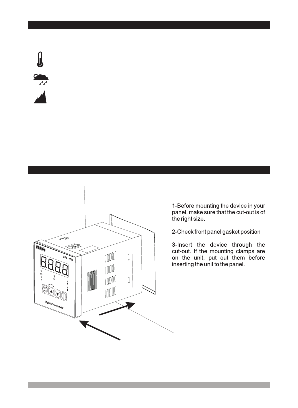
2.5 Panel Mounting
During installation into a metal panel, care should be taken to avoid injury from
metal burrs which might be present. The equipment can loosen from vibration
and become dislodged if installation parts are not properly tightened. These
precautions for the safety of the person who does the panel mounting.
Table des matières
Autres manuels EMKO Panneau de contrôle


