EMKO ESM-4430 Manuel utilisateur

ESM-4430 48x48 DIN 1/16 Process Controller
Instruction Manual. ENG ESM-4430 02 V11 07/13
- 4 4 digits process set (SV) display
(TC, RTD, mV Z, V Z, mA Z)
- Dual or multi point calibration for ZVoltage / Current input
- Adaptation of PID coefficients to the system with Auto-tune and
Self-tune
- Manual/Automatic mode selection for control outputs
- Bumpless transfer
- Programmable heating, cooling and alarm functions for control
outputs
digits process (PV) and
- Universal process input
- Configurable ON/OFF, P, PI, PD and PID control forms
ESM-4430 48 x 48 1/16 DIN
Universal Input PID Process Controller

2
Instruction manual of ESM-4430 Process Controller consists of two main sections.
Explanation of these sections are below. Also, there are other sections which include order
information and technical specifications of the device. All titles and page numbers in instruction
manual are in “CONTENTS” section. User can reach to any title with section number.
Installation:
Physical dimensions, panel mounting, electrical wiring of the device, physical and
electrical installation of the device to the system are explained in this section.
Operation and Parameters:
User interface of the device, how to access to the parameters, description of parameters
are explained in this section.
Also in these sections, there are warnings to prevent serious injury while doing the
physical and electrical mounting or using the device.
Explanation of the symbols which are used in these sections are given below.
This symbol is used to determine the dangerous situations as a result of an electric
shock. User must pay attention to these warnings definitely.
a
cThis symbol is used for safety warnings. User must pay attention to these
warnings.
This symbol is used to determine the important notes about functions and usage of
the device
ABOUT INSTRUCTION MANUAL
i

1.PREFACE............................................................................................................................................
1.1 GENERAL SPECIFICATIONS
1.2 ORDERING INFORMATION
1.3 WARRANTY
1.4 MAINTENANCE
2.INSTALLATION....................................................................................................................................
2.1 GENERAL DESCRIPTION
2.2 DIMENSIONS
2.3 PANEL CUT-OUT
2.4 ENVIRONMENTAL RATINGS
2.5 PANEL MOUNTING
2.6 INSTALLATION MOUNTING CLAMP
2.7 REMOVING FROM THE PANEL
3.ELECTRICAL WIRINGS......................................................................................................................
3.1 TERMINAL LAYOUT AND CONNECTION INSTRUCTION
3.2 ELECTRICAL WIRING DIAGRAM
3.3 VIEW OF THE LABELS
3.4 CONNECTION OF DEVICE SUPPLY VOLTAGE INPUT
3.5 PROCESS INPUT CONNECTION
3.5.1 TC (THERMOCOUPLE) CONNECTION
3.5.2 RTD CONNECTION
3.5.3 PROCESS INPUT CONNECTION OF SERIAL TRANSMITTERS WITH CURRENT
OUTPUT (LOOP POWERED)
3.5.4 PROCESS INPUT CONNECTION OF 3-WIRE TRANSMITTERS WITH CURRENT
OUTPUT
3.5.5 CONNECTION OF TRANSMITTERS WITH VOLTAGE OUTPUT TO PROCESS
INPUT
3.6 GALVANIC ISOLATION TEST VALUES OF ESM-4430 PROCESS CONTROLLER
4.OUTPUT CONNECTION FORMS IN ESM-4430 PROCESS CONTROLLER....................................
4.1 PROCESS OUTPUT (SSR DRIVER OUTPUT) CONNECTION
4.2 ALARM OUTPUT -1 RELAY CONNECTION
4.3 PROCESS OUTPUT OR ALARM OUTPUT -2 RELAY CONNECTION
5.DEFINITION OF FRONT PANEL AND ACCESSING TO THE PARAMETERS..................................
5.1 DEFINITION OF FRONT PANEL
5.2 OBSERVATION OF SOFTWARE REVISION ON THE BOTTOM DISPLAY WHEN POWER
IS ON
5.3 ADJUSTMENT OF PROCESS AND ALARM SET VALUES
5.4 EASY ACCESS DIAGRAM FOR PROGRAM PARAMETERS
5.5 ACCESSING TO THE TECHNICIAN MENU
5.6 CHANGING AND SAVING PARAMETERS
6.PARAMETERS.....................................................................................................................................
6.1 PROCESS / ALARM SET PARAMETERS
6.2 TECHNICIAN PARAMETERS
6.2.1 SELECTION OF PID TUNE AND OPERATION FORM
6.2.2 FUNCTION SELECTION FOR TOP AND BOTTOM DISPLAY
6.2.3 PROCESS INPUT TYPE AND RELEVANT PARAMETERS WITH PROCESS INPUT
6.2.4 PID CONFIGURATION PARAMETERS
6.2.5 PROCESS OUTPUT CONFIGURATION PARAMETERS
6.2.6 ALARM OUTPUT - 1 CONFIGURATION PARAMETERS
6.2.7 ALARM OUTPUT - 2 CONFIGURATION PARAMETERS
6.2.8 GENERAL PARAMETERS
6.2.9 TECHNICIAN PASSWORD
7.FAILURE MESSAGES IN ESM-4430 PROCESS CONTROLLERS...................................................
8.SPECIFICATIONS................................................................................................................................
9.OTHER INFORMATION.......................................................................................................................
CONTENTS
Page 5
Page 41
Page 21
Page 13
Page 8
Page 23
Page 64
Page 65
3
Page 66

4
Manufacturer’s Name : EMKO ELEKTRONIK A.S.
Manufacturer’s Address : DOSAB, Karanfil Sk., No:6,
16369 Bursa, TURKEY
The manufacturer hereby declares that the product:
Product Name : Process Controller Unit
Type Number : ESM-4430
Product Category : Electrical equipment for measurement, control and
laboratory use
Conforms to the following directives :
2006 / 95 / EC The Low Voltage Directive
2004 / 108 / EC The Electromagnetic Compatibility Directive
has been designed and manufactured to the following specifications :
EN 61000-6-4:2007 EMC Generic Emission Standard for the Industrial Environments
EN 61000-6-2:2005 EMC Generic Immunity Standard for the Industrial Environments
EN 61010-1:2001 Safety Requirements for electrical equipment for measurement, control
And laboratory use
When and Where Issued Authorized Signature
th
16 October 2009 Name : Serpil YAKIN
Bursa-TURKEY Position : Quality Manager
EU DECLARATION OF CONFORMITY

5
ESM series process controllers are designed for measuring and controlling temperature
and any process value.They can be used in many applications with their universal process input,
control outputs, selectable alarm functions.
Some application fields and applications which they are used are below:
1.Preface
Application Fields Applications
Glass PID Process Control
Plastic
Petro-Chemistry
Textile
Automative
Machine production industries
Alarm Out-1
(Relay Output)
Process Input
Power Supply
Input
Standard
1.1 General Specifications
ESM-4430
Standard
Standard
Heating-Cooling Function
ON/OFF, PID Operation
Auto-Tune, Self-Tune
Automatic/Manual Operation
Process Out
(SSR Driver Output)
Process Out or
Alarm Out-2
(Relay Output)
Standard
Universal Supply Input
100-240 VV, 50/60Hz
Low Voltage (optional)
Supply Input
24VV50/60Hz ,24VZ
Universal Process Input
TC,RTD, ZVoltage/Current
Control Output
Alarm Output
Control Output

ESM-4430 (48x48 DIN 1/16)
Supply Voltage
A
A
20
1
0
Configurable (Table-1) Table-1
None
BC D E FG HI /
/
U V W Z/
/
Input Type
Output-1
Serial Communication
Scale
BC
E
HI
D
All order information of ESM-4430 are
given on the table at left. User may form
appropriate device configuration from
information and codes that at the table and
convert it to the ordering codes.
Firstly, supply voltage then other
specifications must be determined. Please
fill the order code blanks according to your
needs.
Please contact us, if your needs are
out of the standards.
1.2 Ordering Information
1
01
Output-2
FG
Output-3
02
100-240V V(-15%;+10%) 50/60Hz
24 V V(-15%;+10%) 50/60Hz 24V Z(-15%;+10%)
1
2
Customer (Maximum 240V V(-15%;+10%))50/60Hz
9
01 02
c
Table-1
21
39
41
40
42
43
44
45
22
23
25
27
28
29
31
33
35
37
24
26
30
32
34
36
38
L ,Fe Const DIN43710
PT 100 , IEC751(ITS90)
0...50 mV Z
PT 100 , IEC751(ITS90)
0...5 V Z
0...10 V Z
0...20 mA Z
4...20 mA Z
L ,Fe Const DIN43710
J ,Fe CuNi IEC584.1(ITS90)
K ,NiCr Ni IEC584.1(ITS90)
R ,Pt13%Rh Pt IEC584.1(ITS90)
S ,Pt10%Rh Pt IEC584.1(ITS90)
T ,Cu CuNi IEC584.1(ITS90)
B ,Pt30%Rh Pt6%Rh IEC584.1(ITS90)
E ,NiCr CuNi IEC584.1(ITS90)
N ,Nicrosil Nisil IEC584.1(ITS90)
C , (ITS90)
T ,Cu CuNi IEC584.1(ITS90)
B ,Pt30%Rh Pt6%Rh IEC584.1(ITS90)
E ,NiCr CuNi IEC584.1(ITS90)
N ,Nicrosil Nisil IEC584.1(ITS90)
C , (ITS90)
J ,Fe CuNi IEC584.1(ITS90)
K ,NiCr Ni IEC584.1(ITS90)
-100°C,850°C
-200°C,650°C
-1999,9999
-199.9°C,650.0°C
-100.0°C,850.0°C
-200°C,900°C
-200°C,1300°C
0°C,1700°C
0°C,1700°C
-200°C,400°C
44°C,1800°C
-150°C,700°C
-200°C,1300°C
0°C,2300°C
-199.9°C,900.0°C
-199.9°C,999.9°C
-199.9°C,400.0°C
44.0°C,999.9°C
-150.0°C,700.0°C
-199.9°C,999.9°C
0.0°C,999.9°C
-148°F ,1562°F
-328°F,1202°F
-199.9°F,999.9°F
-148.0°F,999.9°F
-328°F,1652°F
-328°F,2372°F
32°F,3092°F
32°F,3092°F
-328°F,752°F
111°F,3272°F
-238°F,1292°F
-328°F,2372°F
32°F,3261°F
-199.9°F,999.9°F
-199.9°F,999.9°F
-199.9°F,752.0°F
111.0°F,999.9°F
-199.9°F,999.9°F
-199.9°F,999.9°F
32.0°F,999.9°F
Input Type(TC)
Input Type(RTD)
Input Type( ZVoltage and Current)
Scale(°C)
Scale(°C)
Scale
Scale(°F)
Scale(°F)
BC
BC
BC
-1999,9999
-1999,9999
-1999,9999
-1999,9999
0
Relay Output (5A@250 VVat resistive load)
Relay Output (5A@250 VVat resistive load)
SSR Driver Output ( Maximum 17mA, 25VZ)
6
VSymbol means Vac,
ZSymbol means Vdc
Symbol means Vac and VdcW

7
1.3 Warranty
EMKO Elektronik warrants that the equipment delivered is free from defects in material and
workmanship. This warranty is provided for a period of two years. The warranty period starts from
the delivery date. This warranty is in force if duty and responsibilities which are determined in
warranty document and instruction manual performs by the customer completely.
1.4 Maintenance
Repairs should only be performed by trained and specialized personnel. Cut power to the device
before accessing internal parts.
Do not clean the case with hydrocarbon-based solvents (Petrol, Trichlorethylene etc.). Use of
these solvents can reduce the mechanical reliability of the device. Use a cloth dampened in ethyl
alcohol or water to clean the external plastic case.

8
In package ,
- One piece unit
- Two pieces mounting clamps
- One piece instruction manual
A visual inspection of this product for possible damage occured during shipment is
recommended before installation. It is your responsibility to ensure that qualified
mechanical and electrical technicians install this product.
If there is danger of serious accident resulting from a failure or defect in this unit, power
off the system and separate the electrical connection of the device from the system.
The unit is normally supplied without a power switch or a fuse. Use power switch and fuse
as required.
Be sure to use the rated power supply voltage to protect the unit against damage and to
prevent failure.
Keep the power off until all of the wiring is completed so that electric shock and trouble
with the unit can be prevented.
Never attempt to disassemble, modify or repair this unit. Tampering with the unit may
results in malfunction, electric shock or fire.
Do not use the unit in combustible or explosive gaseous atmospheres.
During the equipment is putted in hole on the metal panel while mechanical installation
some metal burrs can cause injury on hands, you must be careful.
Montage of the product on a system must be done with it’s fixing clamps. Do not do the
montage of the device with inappropriate fixing clamp. Be sure that device will not fall
while doing the montage.
It is your responsibility if this equipment is used in a manner not specified in this
instruction manual.
Before beginning installation of this product, please read the instruction
manual and warnings below carefully.
2.Installation
c
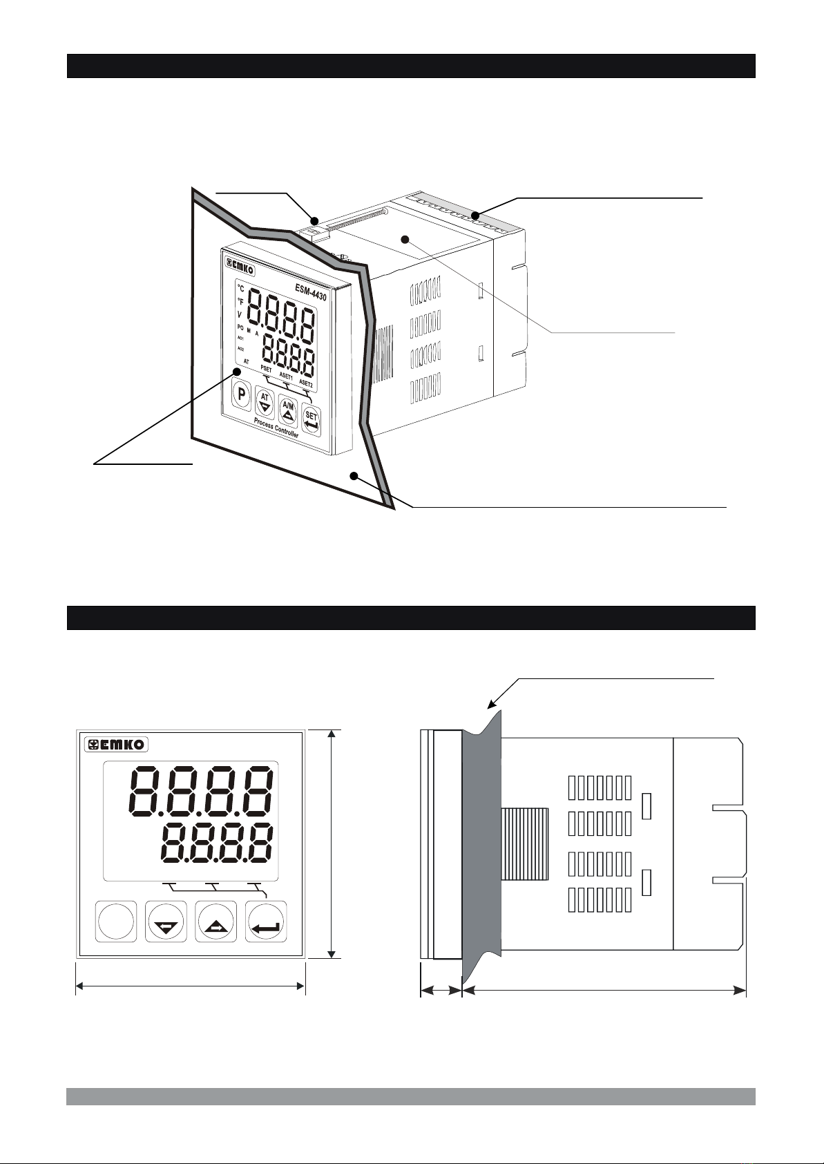
2.1 General Description
2.2 Dimensions
Maximum 5mm / 0.2 inch
48 mm/ 1.89 inch
48mm/ 1.89 inch 76mm / 2.99 inch
11.5 ± 1 mm /0.45 inch
9
Product Label
Terminal protection cover
Mounting Clamp
Front Panel
IP65 protection
NEMA 4X
Panel surface
(maximum thickness 5mm / 0.2 inch)
°C
°F
VV
PO
AO1
AO2
A
AT PSET ASET1 ASET2
M
SET
P
ESM-4430
Process Controller
AT A/M

65 mm/2.56 inch (min)
46 mm/1.81 inch (min)
46 mm/1.81 inch (min)
2.3 Panel Cut-Out
10
65 mm/2.56 inch (min)
Table des matières
Autres manuels EMKO Caisse enregistreuse


Manuels Caisse enregistreuse populaires d'autres marques


Cashmaster
Cashmaster Sigma 105 Manuel utilisateur

Agilent Technologies
Agilent Technologies 53151A Manuel utilisateur

Cashmaster
Cashmaster Sigma 105 Manuel utilisateur

Tellermate
Tellermate TY Manuel d'utilisation et d'entretien

HYOSUNG
HYOSUNG MX-4000W Manuel utilisateur

Cashmaster
Cashmaster Sigma 105 Manuel utilisateur


