Viale Caduti per la Libertà, 4b - 40050 MONTE S. PIETRO - BOLOGNA (ITALY) –
programmato un valore di CPL diverso da 0 (vedi Tab. C).
NOTA 2: la lunghezza di un ciclo è pari al numero delle
uscite moltiplicato per il tempo di PAUSA.
Es. con 10 uscite e Tpausa=10sec. il ciclo dura
10x10=100sec e nel caso di 15 cicli il post lavaggio durerà
100x15=1500 sec=25min.
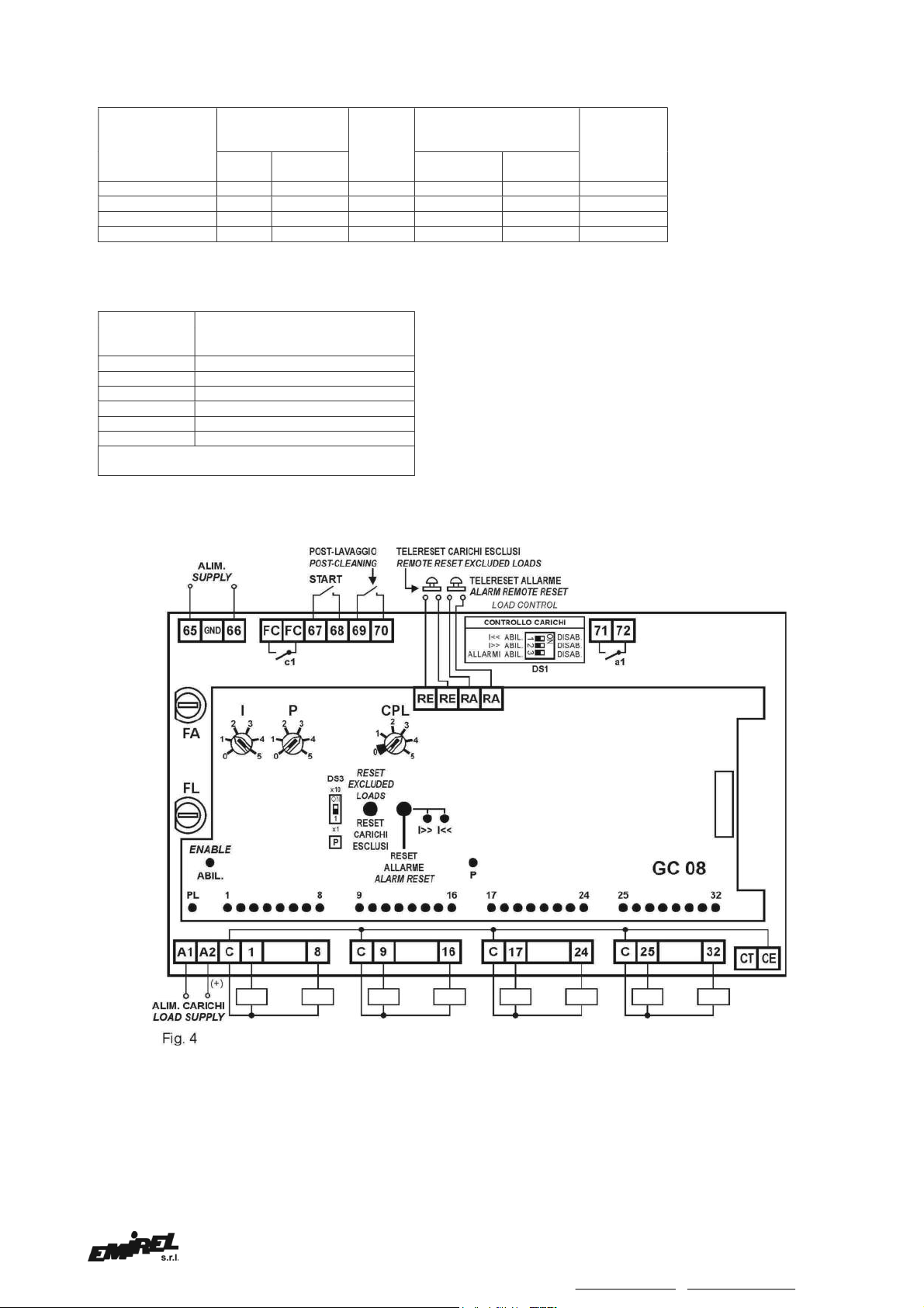
TELERESET CARICHI ESCLUSI
-mors. RE, RE pulsante esterno (NA) libero da potenziale,
per remotare il Reset carichi esclusi.
TELERESET ALLARMI
-mors. RA, RA pulsante esterno (NA) libero da potenziale,
per remotare lo spegnimento dei led I>>, I<< e la
riattivazione del relè A.
USCITE
- Relé A: mors. 71-72 contatto (NA) (3A 230 Vac carico
resistivo) segnala la presenza di anomalie nel controllo
carichi.
- Relé C: mors. Fc, Fc (NA) (3A 230 Vac carico resistivo)
segnala per 2 sec la fine del ciclo.
CARICHI
- mors. 1÷8, 9÷16, 17÷24, 25÷32 (V. Fig. 4) tutti i carichi
hanno un capo in comune da collegare ai morsetti C, l'altro
capo va collegato al pin 1, 2, ecc….
Fusibile carichi (FL) - 5x20 mm rapido.
Le caratteristiche dei carichi e del fusibile FL sono riportate
in Tab. A (in funzione delle tensioni dei carichi). I carichi in
AC sono attivati da Triac con accensione al passaggio
della tensione per 0V. La corrente del carico deve essere
maggiore di 30mA (Holding Current). I carichi in DC (24V)
sono attivati da Transistor con diodo di ricircolo.
ALIMENTAZIONE CICLICO
pin 65-66 3VA 50÷60Hz 24Vac o 115 Vac o 230 Vac
ALIMENTAZIONE CARICHI
pin A1-A2 24Vac÷230 Vac o 24 Vdc
NOTA 3
La tensione di alimentazione ai carichi deve sempre
essere fornita dall’operatore, anche quando è diversa dalla
tensione disponibile per alimentare il ciclico.
Nel caso di alimentazione 24Vdc il + va collegato al pin A2
(la 24Vdc, 32VA, deve essere fornita esternamente, ad
esempio dall'alimentatore AL 20N) (Tab. B).
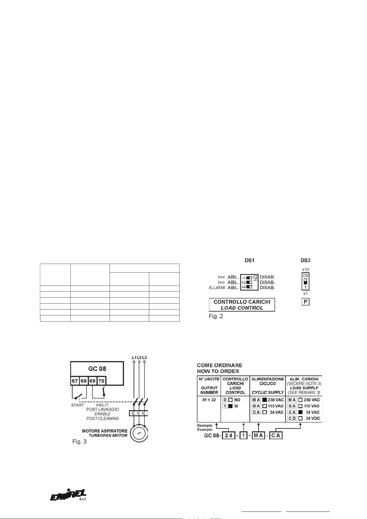
FUNZIONAMENTO
L'operatore deve impostare manualmente:
- la durata dell'impulso mediante I (Tab. A)
- la durata della pausa mediante P (Tab. A)
- il numero di cicli di POST-LAVAGGIO (facoltativo) con
CPL
La frequenza dei lavaggi risulta fissa, il GC 08 entra in
funzione quando il contatto START viene chiuso
(tipicamente quando è acceso il motore dell'aspiratore).
Il consumo di ARIA COMPRESSA non è legato alla
quantità di polvere presente.
CONTROLLO CARICHI
Va scelta in fase d'ordine e viene gestita dal DS1, dai
pulsanti RESET CARICHI ESCLUSI e RESET ALLARMI e
dai led I>> ed I<<.
Per ogni uscita viene rilevata la corrente durante I, e
paragonata con due soglie I<< ed I>> (Tab. B). Se una
delle 2 soglie è superata si accende il led corrispondente e
si eccita il relè A, al prossimo ciclo quella uscita non sarà
più attivata anche dopo una riaccensione del ciclico.
I carichi esclusi sono riattivati con il pulsante RESET
CARICHI ESCLUSI.
REMARK 2: The duration of a cycle is equivalent to the
number of the outputs multiplied by the PAUSE time
Ex: with 10 outputs and Tpause=10sec. the cycle time is
10x10=100sec and in case of 15 cycles the post cleaning
will last 100x15=1500 sec=25min.
TELERESET EXCLUDED LOADS
-pins. RE, RE external push button (NO) voltage free, to
remote the Reset Excluded Loads function.
TELERESET ALARMS
-pins RA, RA external push button (NO) voltage free, to
remote the led I>>, I<< switch off and to reactivate the A
relay.
OUTPUTS
- Relay A: pin 71-72 contact (NO) (3A 230 Vac resistive
load) it detects the presence of anomalies in the Load
- Relay C: pin. Fc, Fc (NO) (3A 230 Vac resistive load) it
signals for 2 sec the end of the cycle.
LOADS
- pins 1÷8, 9÷16, 17÷24, 25÷32 (V. Fig. 4) all the loads have
a wire in common to be connected to the pin C, the other
wire is connected to the pins 1, 2 etc….
Load fuse (FL) - 5x20 mm rapid.
The features of the loads and of the fuse FL are reported in
Tab. A (according to the load voltage). The AC loads are
activated by Triac, when the voltage enters through 0V. The
load current must be higher than 30mA (Holding Current).
The DC (24V) loads are activated by Transistor with diode of
recycle.
DEVICE SUPPLY
pins 65-66 3VA 50÷60Hz 24Vac or 115 Vac or 230 Vac
LOAD SUPPLY
pins A1-A2 24Vac÷230 Vac or 24 Vdc
REMARK 3
The load supply voltage must be always provided by the
user, even when it is different from the voltage used for the
device. In case of voltage supply 24Vdc the wire + is
connected to the pin A2. (the 24Vdc, 32VA, must be
provided from outside the device, for example by a supply
device AL 20N (see TAB B).
MODE OF OPERATION
The operator has to set manually:
- the duration of the pulse by means of I (Tab A)
- the duration of the pause by means of P (TAB A
- the number of the post cleaning cycles (optional) with CPL
The frequency of the cleanings is fixed, the device GC 08
starts working when the contact has been closed (usually
after the turbofan motor is switched on).
The volume of COMPRESSED AIR is not in relation with the
quantity of powder present in the system.
LOAD CONTROL
This function is req