Emec Centurio PRO Manuel utilisateur

1
Read Carefully ! ENGLISH Version
R17-04-20
“CENTURIO PRO” & “CENTURIO POOL”
Controllers Operating Manual
This manual contains safety information that if ignored can
endanger life or result in serious injury. They are indicated by
this icon.
Keep the CONTROLLER protected from sun and water.
Avoid water splashes.
REMOTE CONTROL AND SETUP
www.ermes-server.com
Depending on choosen configuration,controller’s main screen may
appear different and some functions couldn’t be present.

2
Danger!
GENERAL SAFETY GUIDELINES
In emergencies the CONTROLLER should be switched off immediately! Disconnect the power cable
from the power supply!
When installing always observe local regulations!
Manufacturer is not liable for any unauthorized use or misuse of this product that may cause injury,
damage to persons and / or materials.
Caution! CONTROLLER must be accessible at all times for both operating and servicing. Access must not be
obstructed in any way!
Feeder should be interlocked with a no-flow protection device to automatically shut-off connected
pumps when there is no flow!
Pumps and connected accessories must be serviced and repaired by qualified and authorized personnel only!
Always discharge the liquid end before servicing pumps connected to the CONTROLLER!
Empty and rinse the liquid end before work on a connected pump which has been used with hazardous
or unknown chemicals!
Always read chemical safety datasheet!
Always wear protective clothing when handling hazardous or unknown chemicals!
CONTROLLER must be operated / serviced by trained technicians only!
All connection operations must be performed while the CONTROLLER is not connected to main supply!
Missed activation for Min/Max alarm and Maximum Dosing Alarm may cause hazardous overdosing!
NORME CE
EC RULES (STANDARD EC)
NORMAS DE LA CE
Direttiva Bassa Tensione
Low Voltage Directive
Directiva de baja tensión
Direttiva EMC Compatibilità Elettromagnetica
EMC electromagnetic compatibility directive
EMC directiva de compatibilidad electromagnética
2014/35/UE
2014/30/UE
⎬
⎬
3
Introduction
“Centurio PRO” is a multi-measure digital controller capable of simultaneously controlling up to 10 programmable channels
for pH * - Redox (ORP) - Chlorine - Turbidity - Temperature - Combined Chlorine (see Chlorine conguration) features
- Chlorine Total (see Chlorine function for the conguration) - Tracers - Conductivity - Dissolved oxygen - Potentiostatic.
The controller has 6 setpoints outputs, 6 proportional outputs, 6 mA outputs, 1 probe cleaning output and 5 product tank
level inputs. The controller can be connected to a PC, even remotely, for remote control of the system via USB, RS485,
MODEM GSM or GPRS, ETHERNET. The working scales of the controller are:
pH: from 0 to 14 pH
Redox (ORP): from 0 to 1000 mv
Chlorine (combined / total): from 0 to 10 mg/l
Tracers: from 0 to 999.9 PPM
mA Input 0/4-20 mA
Turbidity: from 0 to 9999 NTU
Potentiostatic: 5 PPM
Temperature: from 0 to 200 ° C
Conductivity: from 0 to 300.0 mS
Conductivity Ind.: from 0 to 30.000 uS
Dissolved Oxygen: 0 to 20 mg/l
Conductivity and optional modules: pH, Tracer, Chlorine Meter with Proportional and Digital outputs, Generic mA channel
The wheel and the touch screen
The controller can be operated using both the wheel and the touch screen controls. The wheel is located below the
screen and can be both rotated and pressed to conrm operations.
Tap to conrm changes (right corner screen)
Tap to discard changes and return to previous menu (left corner screen)
Tap to return to main screen
A RED COLOR BAR WITHIN A CHANNEL REQUIRES USER ATTENTION - TAP ON IT FOR FURTHER INFORMATION
The capacitive touch screen could not work while wearing gloves. If you need to wear them for safety reason please use a
capacitive stylus to operate controller’s screen. Some functions can be performed using the touch screen only.
Swipe or Tap
Rotate and Press

4
Mainboard connections
Unplug CONTROLLER from main power supply then perform connections by following the picture below.
For easy understanding the board has been divided into two parts: I/O connections and Power - Relays connections.
For mA outputs and optionals connections refer to page 35.
Fuses:
F1: Main Power Fuse (6,3A T)
F2: CONTROLLER Fuse (3.15A T)
S1(+) - S2(GND): Standby
PEF: Connector for PEF LIGHT ALARM
FOUT: Remove jumper to disable L(LIVE) from RELAYS OUTPUTS
Power and Relays Connections:
L(Live) - E(Earth) - N(Neutral): Main power supply 230VAC (85-264VAC, 50/60Hz) or 24VAC* 50/60 Hz *see controller’s label
LF (LIVE FUSE PROTECTED): Live input for motorized EV
41(N.C. contact) - 42(Common) - 43(N.O. contact): Free of voltage contact (max insulation 250V) RELAY n.1
44(N.C. contact) - 45(Common) - 46(N.O. contact): Free of voltage contact (max insulation 250V) RELAY n.2
47(L) - 53(E) - 59(N): Setpoint RELAY n.3
48(L) - 54(E) - 60(N): Setpoint RELAY n.4
49(L) - 55(E) - 61(N): Setpoint RELAY n.5
50(L) - 56(E) - 62(N): Setpoint RELAY n.6
51(L) - 57(E) - 63(N): Setpoint RELAY n.7
52(L) - 58(E) - 64(N): Setpoint RELAY n.8
Power and Relays ConnectionsI/O Connections
Warning: Connections must be perfomed by qualified and trained personnel only
F1
F2
1 2 3 4 5 6 7 8 S1S2
9 10 11 12 13 14 15 16 17 18 19 20 21 22 23 24
25 26 27 28 29 30 31 32 33 34 35 36 37 38 39 40
47 48 49 50 51 52 L
53 54 55 56 57 58 E
59 60 61 62 63 64 N
LF
PEF
FOUT
41 42 43 44 45 46

5
I/O Connections:
1(+) ; 2(-): Pulse Sender Water Meter input n.1 (WM1) max 300Hz
3(+) ; 4(-): Pulse Sender Water Meter input n.2 (WM2) max 300Hz
5(+ Brown) - 6(Black) - 7/8(- Blue ; GND): Flow sensor mod. “SEPR” (don’t remove jumper between blocks 7 and 8)*
*to use it as free of voltage contact leave jumper on blocks 7 and 8 and use blocks 5 and 6 as contact
9(+) ; 10(-): Level input n.1
11(+) ; 12(-): Level input n.2
13(+) ; 14(-): Level input n.3
15(+) ; 16(-): Level input n.4
17(+) ; 18(-): Level input n.5
19(+) ; 20(-): Level input n.6
21(+) ; 22(-): Level input n.7
23(+) ; 24(-): Level input n.8
25(-) ; 26(+): Proportional pump (driven by pulses, optocoupled signal) output n.1 NPN max 50mA / 24VDC
27(-) ; 28(+): Proportional pump (driven by pulses, optocoupled signal) output n.2 NPN max 50mA / 24VDC
29(-) ; 30(+): Proportional pump (driven by pulses, optocoupled signal) output n.3 NPN max 50mA / 24VDC
31(-) ; 32(+): Proportional pump (driven by pulses, optocoupled signal) output n.4 NPN max 50mA / 24VDC
33(-) ; 34(+): Proportional pump (driven by pulses, optocoupled signal) output n.5 NPN max 50mA / 24VDC
35(-) ; 36(+): Proportional pump (driven by pulses, optocoupled signal) output n.6 NPN max 50mA / 24VDC
37(-) ; 38(+): Proportional pump (driven by pulses, optocoupled signal) output n.7 NPN max 50mA / 24VDC
39(-) ; 40(+): Proportional pump (driven by pulses, optocoupled signal) output n.8 NPN max 50mA / 24VDC
Modules Code Numbers:
Warning: Connections must be perfomed by qualified and trained personnel only
Power and Relays Connections
must be opened inserting a
screwdriver’s tip in the upper part
of module and inserting the wire
in the lower part as shown in left
picture!
Wires in the “I / O Connections” terminals can be inserted
by rst removing the block from the board to facilitate the
installation operation.
00274971 PH
00280181 PS
00274981 RH
00276381 SCL
00281431 TORB2
00280101 TORB2IM
00277391 TORBH
00274991 CD
00276991 CDIND
00277001 CDSIND
00278101 CL4/5/6
00280931 EOLUM
00281071 FL
00279561 INPUT mA
00280361 OUT mA
00276391 TRC

6
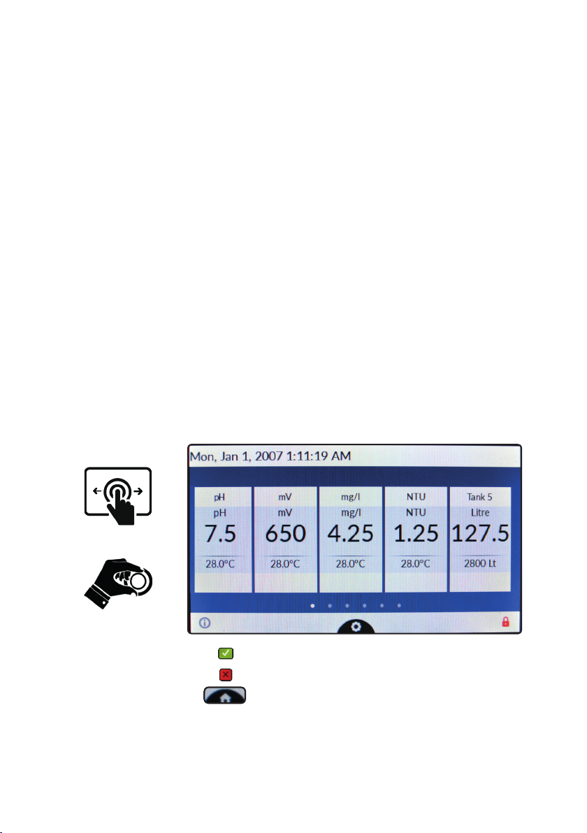
“Centurio PRO” main screen.
For more info about channel status (alarms, readings, etc..) tap on it for a “in-depth” explanation popup.
Channels / Units
Channels readings
Channels status
Local Date / Time Network Connection
Tap on gear icon for settings menu
These dots represent how many screens are available for actual viewing.
Swipe on screen to scroll between them.
Pulse sender water meters for input / bleed (see settings to congure)
For more info about serial number / ERMES code tap on it to see an explanation popup.
Red icon requires user attention. Please tap on it for further information.
For more info about ETHERNET / USB / ERMES network connection and settings tap on it.
Please note: main screen aspect may change due to installed modules / channels available
(1 conductivity channel for basic tower functions plus up to 4 more channels)
Tap on “X” icon to discard changes / Tap on “tick” icon to save changes.
Actual screen can be scrolled up or down for more options.

7
“Centurio PRO” basic settings.
Basic settings are: PASSWORDs, Time & Date, Language and International Units.
Standard settings are: Probes calibration and working modes (bleed - inhibitor - biocide).
Advanced settings are: Flow meter, Alarm and Communication (WiFi, Mobile, ERMES) menu.
All these three settings must be set in order to properly operate the CONTROLLER.
PASSWORD for main menu (settings) access.
To grant access into main menu tap on from main screen and enter the PASSWORD using the keypad on the right
side of the screen. Default PASSWORD is 0000 (factory preset).
To set a new PASSWORD choose “PASSWORD ” from “Settings” menu and enter a four numbers code. Conrm
changes to activate the new PASSWORD.
Lost PASSWORD ?
Please dont’ forget the PASSWORD (if changed). In the unfortunate event, please call your local distributor for unlocking procedure.
There is no way for you to recover a lost PASSWORD.

8
International.
Before to program the controller please setup Language, Location and local Time & Date (Settings / International).Since
the controller activities are based on time is essential to setup time and date prior to anything. Within International menu
please choose language and location for proper units format.
Based on location units change according to local rules. To end procedure tap on tick icon for each change.
EUROPE IS (Internationl Standard) USA
Date (DD/MM/YY) Date (MM/DD/YY)
Time 24h Time AM / PM
°C Celsius °F Farhenheit
Liters Gallons

9
“Centurio PRO” standard settings.
Standard settings are: Probes calibration and operating modes (bleed - inhibitor - biocide). To calibrate each channel
select it within main menu. Channels availability is based on modules conguration. The controller will automatically add
the proper channel when a new module is installed and detected.
Conductivity calibration menu.
This menu includes probe choice, conductivity calibration , temperature compensation and manual or automatic temperature
compensation. Conductivity calibration procedure involves a zero calibration (First Point) and a 2nd calibration point (Second
Point) that requires a buffer solution with value near working range. Furthermore Temperature and Automatic Compensation
must be set. Note: This procedure assumes that CONTROLLER is correctly installed and congured, connected
to a working probe. Calibrate using plant’s temperature otherwise unattended results might occur. If something
wrong occurs use RECOVERY CALIBRATION to restore to previous calibration.
First Point & Second Point.
During this procedure probe must be dry and clean and not installed in plant. Tap on “First Point” (zero) and conrm it.
Tap on “Second point”, dip probe’s head into buffer solution and wait until reading value is stable, enter buffer solution
value and conrm it.
Temperature Compensation (if available)
Conductivity measurements are temperature dependent. The degree to which temperature affects conductivity varies
from solution to solution and can be calculated using the following formula: C25 = C / {1+[a/100(t-25)]} where: C25 =
slution conductivity at 25°C, C = conductivity at operating temperature, a = temperature coefcient of solution %/°C.
Probe read value
(uS or ppm)
Alpha
(a)
Temperature
(°C / °F)
Displayed Value
(us or ppm)
5227 1.2 35°C / 95°F 4934
4524 3.5 27°C / 80.6°F 4228
3924 2.1 40°C / 104°F 2984
Samples alphas (a) are listed in the table above. To determine that “a” of other solutions, simply measure conductivity at
a range of temperatures and graphic the change in conductivity versus the change in temperature. “Centurio PRO” has
either xed or adjustable automatic temperature compensation referenced to a standard temperature of 25°C.
Otherwise choose automatic temperature compensation and set % Alpha value.

10
Chlorine calibration menu.
Chlorine calibration procedure is based on installed chlorine probe and may involve one or two calibration points depen-
ding on probes’ model (see table at next page). From main menu choose “Chlorine” then tap on Calibration”. Installed
probe will be automatically detected and according to model a one or two points calibration will be enabled.
Note: This procedure assumes that CONTROLLER is correctly installed and congured, connected to a working
probe. Calibrate using plant’s temperature otherwise unattended results might occur. If something wrong occurs
use RECOVERY CALIBRATION to restore to previous calibration.
Two points calibration method.
During this procedure probe must be dry and clean and not installed in plant. Use chlorine free water (or a carbon lter
system) and dip probe’s head into it, wait until reading is stable, then ap on “First Point” (zero) to conrm it.
For Second point calibration use a plant’s sample water and analyze it using a DPD system to obtain value. Enter this
value as second point calibration and conrm it.
One point calibration method (second point).
For Second point calibration use a plant’s sample water and analyze it using a DPD system (photometer) to obtain
value. Enter this value as second point calibration and conrm it.
Carbon Filter System Photometer
Ce manuel convient aux modèles suivants
1
Table des matières
Autres manuels Emec Contrôleurs


