Elenco Electronics FG-600K Guide de l'utilisateur

FUNCTION GENERATOR KIT
MODEL FG-600K
Assembly and Instruction Manual
Elenco Electronics, Inc.
Copyright © 1999 Elenco Electronics, Inc. Revised 2001 REV-A 753033

PARTS LIST
If any parts are missing or damaged, see instructor or bookstore. DO NOT contact your place of purchase as
they will not be able to help you.
Contact Elenco Electronics (address/phone/e-mail is at the back of this manual) for additional assistance, if needed.
RESISTORS
Qty Symbol Description Part #
1 R2 10kΩPotentiometer 192531
1 R3 100kΩPotentiometer 192612
1 R6 (201) Resistor Chip 200Ω5% 1/8W 196320
1 R1 (621) Resistor Chip 620Ω5% 1/8W 196362
1 R5 (392) Resistor Chip 3.9kΩ5% 1/8W 196434
1 R7 (822) Resistor Chip 8.2kΩ5% 1/8W 196484
1 R8 (103) Resistor Chip 10kΩ5% 1/8W 196514
1 R4 (223) Resistor Chip 22kΩ5% 1/8W 196522
1 R9 (104) Resistor Chip 100kΩ5% 1/8W 196614
CAPACITORS
Qty Symbol Value Description Part #
1 C6 820pF Capacitor Chip 228297
1C5 .01µF Capacitor Chip 241095
1C4 .1µF Capacitor Chip 250195
1C3 1µF Lytic Chip 260127
3 C2, C7, C8 10µF Lytic Chip 271024
1 C1 100µF 16V Lytic Radial 281044
1 C9 1000µF 16V Lytic Radial 291044
SEMICONDUCTORS
Qty Symbol Value Description Part #
1 U1 XR-2206 Integrated Circuit Surface Mount 332206SM
MISCELLANEOUS
Resistor
Chip
PARTS IDENTIFICATION
PC Mount
Potentiometer
Qty Description Part #
1 PC Board FG-600 511002
2 Switch Slide PC Mount (S2, S3) 541009
1 Switch Rotary 2p 6 pos. (S1) 542207
1 Battery Snap 9V 590098
1 Top Panel 614109
3 Knob 622009
1 Case Black Plastic 623003LP
2 Spacer 5/8” 624432
1 Binding Post Black 625031
3 Hex Nut for Binding Post 625031HN
3 Lockwasher Binding Post 625031LW
Qty Description Part #
2 Binding Post Green 625033
4 Screw 4-40 x 1/4” Phillips Black 641433
3 7mm Hex Pot Nut 644101
1 9mm Hex Switch Nut 644102
2 8mm x 14mm Flat Washer 645101
1 9mm x 15mm Flat Washer 645103
1 Handle 666600
2” Weather Strip 790007
12” Wire 22ga. Black Solid 814120
1 Solder 9ST4
Binding Post with
Nuts & Lockwasher
Knob
471
Integrated Circuit
Battery
Snap
Slide Switch
Rotary Switch
-1-
Spacer Capacitors
Chip
Lytic Chip Lytic Radial

-2-
INTRODUCTION
Assembly of your FG-600 Function Generator will prove to be an exciting project and give much satisfication
and personal achievement. The FG-600 contains a complete function generator capable of producing sine,
square and triangle wave forms. The frequency of this generator can be contiuously varied from 1Hz to 1MHz
in 6 steps. A fine frequency control makes selection of any frequency in between easy. The amplitude of the
wave forms are adjustable from 0 to 3Vpp. This complete function generator system is suitable for
experimentation and applications by the student. The entire function generator is comprised of a single XR-
2206 monolithic IC and a limited number of passive circuit components.
The FG-600 uses surface mounted components. By building this kit, you will obtain an interesting electronic
device and also gain valuable experience in surface mount technology.
SPECIFICATIONS
OUTPUT:
• Waveforms: Sine, Triangle, Square
• Impedance: 600Ω+10%.
• Frequency: 1Hz - 1MHz in 6 decade steps with variable ranges.
SINE WAVE:
• Amplitude: 0 - 3Vpp.
• Distortion: Less than 1% (at 1kHz).
• Flatness: +0.05dB 1Hz - 100kHz.
SQUARE WAVE:
• Amplitude: 8V (no load).
• Rise Time: Less than 50ns (at 1kHz).
• Fall Time: Less than 30ns (at 1kHz).
• Symmetry: Less than 5% (at 1kHz).
TRIANGLE WAVE:
• Amplitude: 0 - 3Vpp.
• Linearity: Less than 1% (up to 100kHz).
POWER REQUIREMENTS:
• Standard 9V Battery
OPERATING TEMPERATURE:
• 0OC TO 50OC.
PARTS VERIFICATION
Before beginning the assembly process, familiarize yourself with the components and this instruction book.
Verify that all parts are present. This is best done by checking off each item against the parts list.
Care must be taken when handling the chip resistors and capacitors.
They are very small and are easily lost. Chip resistors are marked
with their component value. The first 2 digits are the first 2 digits of
the resistance in ohms. The last digit gives the number of zeros
following the first 2 digits. The resistor shown at right is therefore
3900Ω.
The values of the chip capacitors are not marked on the component.
The chip capacitor C6 (820pF) is in the bag with the chip resistors,
the chip capacitor C5 (.01µF) is in the bag with the lytic capacitors
and the chip capacitor C4 (.1µF) is in the bag with the IC. To avoid
mixing these parts up, they should not be taken out of their packages
until just before they are soldered to the PC board.

-3-
Introduction
The most important factor in assembling your FG-600K Function Generator Kit is good soldering techniques.
Using the proper soldering iron is of prime importance. A small pencil type soldering iron of 25 - 40 watts is
recommended.The tip of the iron must be kept clean at all times and well tinned.
Safety Procedures
• Wear eye protection when soldering.
•
Locate soldering iron in an area where you do not have to go around it or reach over it.
•Do not hold solder in your mouth. Solder contains lead and is a toxic substance. Wash your hands
thoroughly after handling solder.
• Be sure that there is adequate ventilation present.
Assemble Components
In all of the following assembly steps, the components must be installed on the top side of the PC board unless
otherwise indicated. The top legend shows where each component goes. The leads pass through the
corresponding holes in the board and are soldered on the foil side.
Use only rosin core solder of 63/37 alloy.
DO NOT USE ACID CORE SOLDER!
CONSTRUCTION
Solder Soldering Iron
Foil
Solder
Soldering Iron
Foil
Component Lead
Soldering Iron
Circuit Board
Foil
Rosin
Soldering iron positioned
incorrectly.
Solder
Gap
Component Lead
Solder
Soldering Iron
Drag
Foil
1. Solder all components from
the copper foil side only.
Push the soldering iron tip
against both the lead and
the circuit board foil.
2. Apply a small amount of
solder to the iron tip. This
allows the heat to leave the
iron and onto the foil.
Immediately apply solder to
the opposite side of the
connection, away from the
iron. Allow the heated
component and the circuit
foil to melt the solder.
1. Insufficient heat - the
solder will not flow onto the
lead as shown.
3. Allow the solder to flow
around the connection.
Then, remove the solder
and the iron and let the
connection cool. The
solder should have flowed
smoothly and not lump
around the wire lead.
4.
Here is what a good solder
connection looks like.
2. Insufficient solder - let the
solder flow over the
connection until it is
covered. Use just enough
solder to cover the
connection.
3. Excessive solder - could
make connections that you
did not intend to between
adjacent foil areas or
terminals.
4. Solder bridges - occur
when solder runs between
circuit paths and creates a
short circuit. This is usually
caused by using too much
solder. To correct this,
simply drag your soldering
iron across the solder
bridge as shown.
What Good Soldering Looks Like
A good solder connection should be bright, shiny,
smooth, and uniformly flowed over all surfaces.
Types of Poor Soldering Connections

-4-
Assemble Surface Mount Components
The most important factor in assembling your FG-600 Function Generator Kit is good soldering techniques.
Using the proper soldering iron is of prime importance. A small pencil type iron of 10-15 watts is recommended.
A sharply pointed tip is essential when soldering surface mount components. The tip of the iron should be kept
clean and well tinned at all times. Many areas on the printed circuit board are close together and care must be
given not to form solder shorts. Solder shorts may occur if you accidentally touch an adjacent foil, particularly
a previously soldered connection, using too much solder, or dragging the iron across adjacent foils. If a solder
short occurs, remove it with your hot iron. Use only rosin core solder of 60/40 alloy. Before soldering the FG-
600 board should be taped to the workbench to keep it from moving when touched with the soldering iron. For
a good soldering job, the areas being soldered must be heated sufficiently so that the solder flows freely. When
soldering surface mount resistors and capacitors, the following procedure may be used:
1. Using tweezers, place the surface mount component on the PC board
pads and secure in place with tape.
2. Apply a small amount of solder to the soldering iron tip. This allows the
heat to leave the iron and flow onto the foil.
3. Place the iron in contact with the PC board foil. Apply a small amount of
solder simultaneously to the foil and the component and allow them to
melt the solder.
4. Remove the iron and allow the solder to cool. The solder should have flowed freely and not lump up around
the component.
5. Remove the tape and solder the other side of the component.
When soldering the transistors, diodes and integrated circuits, the following procedure may be used:
1. Place the component on the PC board pads and secure in place with tape.
2. Apply a small amount of solder to the soldering iron tip.
3.
Place the soldering iron tip on top of the component lead to be soldered and apply solder simultaneously to
the lead and the PC board foil.
4. Remove the iron and allow the solder to cool.The solder should have
flowed freely and not lump up around the component.
After a component is completely soldered, each solder joint should be
inspected with a magnifying glass. If the solder has not flowed smoothly, a
bad solder joint is indicated. This occurs when the component and pad have
not been heated sufficiently. To correct, reheat the connection and if
necessary add a small amount of additional solder.
Another way to solder surface mount components is as follows:
1. Apply a small amount of solder to the soldering iron tip.
2. Using tweezers, hold the component on the PC board pads.
3. Apply the soldering iron simultaneously to the component and pad and
allow the solder to flow around the component.
4. Remove the soldering iron and allow the connection to cool.
Solder
Tape
Iron
Solder
Tweezers
Iron

-5-
ASSEMBLE COMPONENTS TO THE PC BOARD
Care must be given to identifying the proper components and in good soldering habits. Refer to the soldering
tips section in this manual before you begin installing the components. Place a check mark in the box after
each step is complete.
R1 - 620Ω5% 1/8W Res. Chip
(621)
C7 - 10µF Lytic Chip
(see Figure A)
U1 - XR-2206P IC Surface Mnt.
(see Figure B)
R9 - 100kΩ5% 1/8W Res.Chip
(104)
R8 - 10kΩ5% 1/8W Res. Chip
(103)
R5 - 3.9kΩ5% 1/8W Res. Chip
(392)
R6 - 200Ω5% 1/8W Res. Chip
(201)
R4 - 22kΩ5% 1/8W Res. Chip
(223)
C5 - .01µF Capacitor Chip
(in the bag with lytic capacitors.)
C4 - .1µF Capacitor Chip
(in the bag with IC.)
C3 - 1µF Lytic Chip
(see Figure A)
C6 - 820pF Capacitor Chip
(in the bag with resistors.)
C2 - 10µF Lytic Chip
(see Figure A)
C8 - 10µF Lytic Chip
(see Figure A)
R7 - 8.2kΩ5% 1/8W Res. Chip
(822)
Figure B
Mount IC with pin 1 as shown on the PC board
illustration.
Figure A
This capacitor is
polarized, be sure
that the (+) and (--)
sides are positioned
correctly.

-6-
ASSEMBLE COMPONENTS TO THE PC BOARD
Figure E
Mount the pots down flush with
the PC board. For R2, install nut.
Figure D
Electrolytic capacitors have polarity. Be sure to
mount them with the negative (--) lead (marked
on side) in the correct hole. Bend the electrolytic
capacitors as shown.
S1 - 6 position Rotary Switch
(see Figure C)
C1 - 100µF 16V Electrolytic
(see Figure D)
C9 - 1000µF 16V Electrolytic
(see Figure D)
BT - Battery Snap
(see Figure F)
S3 - Slide Switch
Figure C
Mount down flush with PC
board.
Cut off
tab
Figure F
Thread the battery snap wires through the hole in the PC board from the solder
side as shown. Solder the red wire to the BT+ point and the black wire to the BT-
- point on the PC board.
Figure G
Form a discarded piece of an
electrolytic lead into a jumper wire
by bending the wire into the correct
length and mounting it to the PC
board.
Black Wire (BT--)
Red Wire (BT+)
Black Wire (BT--)
Red Wire (BT+)
R3 - 100kΩPot PC Mount
(see Figure E)
R2 - 10kΩPot PC Mount
7mm Hex Pot Nut
(see Figure E)
Jumper Wire
Jumper Wire
(see Figure G)
J1 - 3” Black Wire
J2 - 3” Black Wire
J3 - 3” Black Wire
(see Figure H)
S2 - Slide Switch
Figure H
Cut three 3” wires and strip 1/4” of
insulation off of both ends of the
wires. Solder these wires to the
points J1, J2 and J3.
Cut off tab

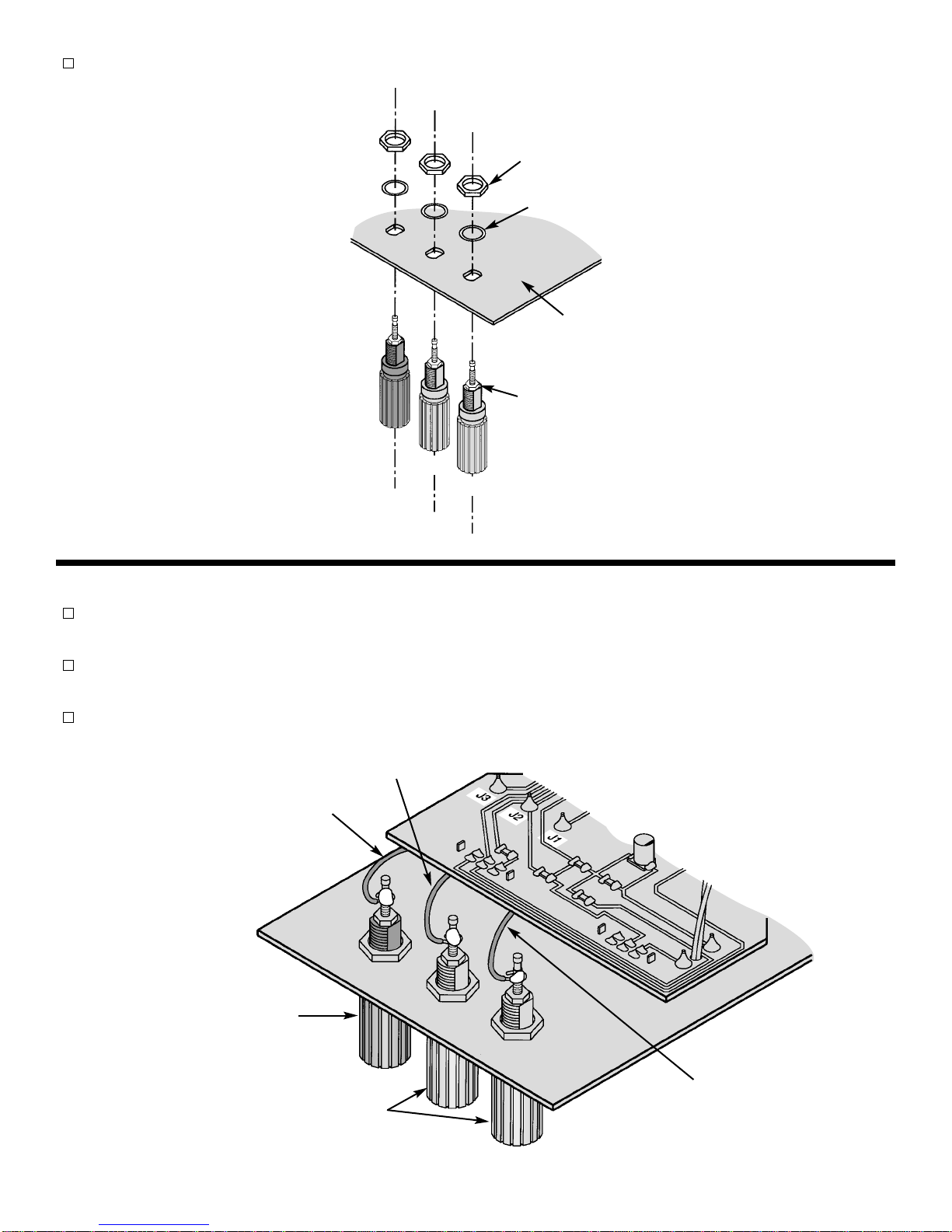
Install the colored binding posts to the panel as shown in Figure I. Use the hardware shown in the figure.
-7-
Nut
Lockwasher
Binding Post
Green
Black
Backside of
Panel
Small Nut
Green
Figure I
Figure J
Black Binding Post
Green Binding Posts
Wire from J3
Wire from J2
Wire from J1
WIRING
Attach the 3” black wire from point J3 on the PC board, to the black binding post, then solder into place (see
Figure J).
Attach the 3” black wire from point J2 on the PC board, to the middle green binding post, then solder into
place (see Figure J).
Attach the 3” black wire from point J1 on the PC board, to the other green binding post, then solder into place
(see Figure J).

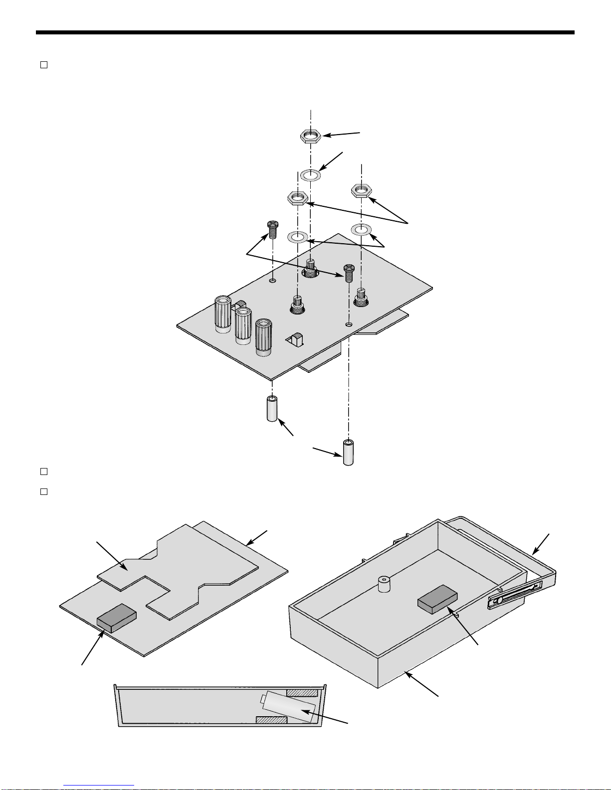
Install the handle as shown in Figure L.
Cut two pieces of weather stripping. Remove the protective backing and place a piece of weather strip on the top
panel in the location shown in Figure L. Then, place the other piece on the case in the location shown.
FINAL ASSEMBLY
Place the washers onto their locations as shown in Figure K, being careful to check the sizes. Then, tighten
the hex nuts onto the potentiometers noting their size as shown in Figure K. Finally, fasten the spacers onto
the top panel with two 4-40 x 1/4” black screws.
-8-
8mm x 14mm Washers
7mm Hex Pot Nuts
9mm Hex Switch Nut
Figure K
9mm x 15mm Flat Washer
4-40 x 1/4”
Screws
Spacers
Weather Strip
Weather Strip
The battery should fit like this.
PC Board Top Panel
Bottom Case
Battery
Figure L
Handle

-9-
Attach the battery snap to the battery. Insert the PC board assembly with the panel and battery into the case
(as shown in Figure L). Insert two 4-40 x 1/4” screws into the bottom case in positions shown in Figure M
and tighten in place.
Turn the shafts on the two potentiometers and rotary switch fully counter-clockwise. Push the three knobs
onto the shafts so that the line on the knob is on the point as shown in Figure N.
TESTING THE FG-600 FUNCTION GENERATOR
The unit may be tested by following the 4 steps listed below. Should any of these tests fail, refer to the
Troubleshooting Guide.
1) Set the switches and pots as follows:
On/Off On
Range 10
Frequency Maximum (clockwise)
Amplitude Maximum (clockwise)
Sine/Triangle Set Sine/Triangle switch to Sine position
4-40 x 1/4” Screws
Figure M
Figure N
Table des matières
Autres manuels Elenco Electronics Onduleur

Elenco Electronics
Elenco Electronics GF-8026 Manuel utilisateur

Elenco Electronics
Elenco Electronics GF-8025 Manuel utilisateur

Elenco Electronics
Elenco Electronics SM-9600K Manuel utilisateur

Elenco Electronics
Elenco Electronics FG-500 Manuel utilisateur

Elenco Electronics
Elenco Electronics GFG-8016D Manuel utilisateur

Elenco Electronics
Elenco Electronics FG-500K Guide de l'utilisateur

Elenco Electronics
Elenco Electronics GF-8056 Manuel utilisateur