
Element14 mi:node Manuel utilisateur

User Manual V3.1
Element14 | element14.com/minode 1
mi:node
User Manual

User Manual V3.1
Element14 | element14.com/minode 2
Table of Contents
1) Introduction ....................................................................................................................................................... 3
1.1 Overview .................................................................................................................................................... 3
1.2 Features ..................................................................................................................................................... 3
1.3 Kit Contents................................................................................................................................................ 3
2) Getting Started................................................................................................................................................... 5
2.1 The Connector Board ................................................................................................................................. 5
2.2 E-Brick Connectors ..................................................................................................................................... 5
2.3 Inputs ......................................................................................................................................................... 6
a) Analog In/PWM.......................................................................................................................................... 6
b) Digital IO..................................................................................................................................................... 7
c) I2C (Inter-Integrated Circuit)...................................................................................................................... 7
2.4 Pin Mapping ............................................................................................................................................... 7
3) Usage.................................................................................................................................................................. 8
3.1 Programming Using mi:node ..................................................................................................................... 8
3.2 Working With mi:node Libraries ................................................................................................................ 8
3.3 Working Without mi:node Libraries......................................................................................................... 11
3.4 Module Usage & API Reference............................................................................................................... 11
a) Light Sensor.............................................................................................................................................. 11
b) Temperature and Humidity Sensor (DHT11)............................................................................................ 13
c) Sound Sensor ........................................................................................................................................... 16
d) Rotary Module ......................................................................................................................................... 17
e) Mini Fan Module ...................................................................................................................................... 20
f) Speaker Module ....................................................................................................................................... 22
g) PIR Sensor Module ................................................................................................................................... 23
h) RGB LED Module ...................................................................................................................................... 25
i) Switch Module ......................................................................................................................................... 27
j) Relay Module ........................................................................................................................................... 30
4) Appendix .......................................................................................................................................................... 32
4.1 Microsoft MakeCode................................................................................................................................ 32
4.2 Support..................................................................................................................................................... 32

User Manual V3.1
Element14 | element14.com/minode 3
1) Introduction
1.1 Overview
The mi:node kit is a modular, safe and easy to use group of accessories that work along the BBC
micro:bit to help introduce children to the Internet of Things (IoT) –a term created to describe
the growing network of devices that are able to connect to the Internet, collect data and
exchange information.
With this kit there is no need for soldering, just connect and use. The construction of a working
circuit can be easily completed in less than one minute.
1.2 Features
Includes sensors for environmental and physical monitoring, as well as user interface modules
(such as a switch) to allow a number of exciting projects including wearable applications and
smart home devices.
Rich education guide with lesson documentation and many project stories.
Expandable
Reusable
1.3 Kit Contents
Image 1.3 –mi:node Kit Contents

User Manual V3.1
Element14 | element14.com/minode 4
Category
#
Module
Qty
Connector
Type
Description
Connect
Board
1
Connect Board
1
NA
A bridge between the micro:bit and the
mi:node sensor modules
Sensor
Modules
(10)
2
Light Sensor
1
Analog Input
Detects the intensity of light in an
environment
3
Speaker
1
Analog
Output/
PWM
Voice output amplifier
4
Temperature and
Humidity Sensor
1
Analog Input
Senses temperature and humidity
within the environment
5
Sound Sensor
1
Analog Input
Detects the sound strength within an
environment
6
Mini Fan
1
Analog
Output/
PWM
A connector board for the DC Motor and
Orbit Fan
7
Relay
1
Digital Output
A digital switch used to control high-
voltage electrical devices, up to a
maximum of 250V
8
Rotary Angle
1
Analog Input
A switch with a 0 - 300 degree dial used
to control voltage output from 0V to
maximum
9
PIR Motion Sensor
1
Digital Input
Senses motion; usually human
movement within range
10
Switch
1
Digital Input
Used to switch voltage ON/OFF
11
RGB LED
1
Digital Output
A colorful Light Emitting Diode. The
color and brightness can be
programmed.
Accessories
12
Orbit Fan
1
Analog Input
Small handheld fan (Located under the
Connect Board in the box)
13
DC Motor
1
Analog
Output/
PWM
Direct Current (DC) motor used to run
the Orbit Fan using the Mini Fan
connector board. Can be used to run
other small devices as well.
Cables
14
E-Brick Connector
Cable
8
N/A
Double ended cables of two different
lengths used to connect sensor modules
to the Connect Board.
2 x 20cm cable
6 x 10cm cable
15
Micro-USB to USB
2
N/A
Two cables, One for power input to the

User Manual V3.1
Element14 | element14.com/minode 5
Cable
Connect Board.
One for micro:bit program upload.
Table 1.3 –Kit Contents
* Note: BBC micro:bit not include; sold separately.
2) Getting Started
2.1 The Connector Board
The kit is comprised of a Connector Board and several sensor modules. The Connect Board is a
bridge between the BBC micro:bit and the mi:node sensor modules. It converts the BBC
micro:bit edge connector into several e-brick connectors. The sensor modules can then easily
be attached to it using the provided e-brick cables.
Image 2.1 –mi:node Connect Board
2.2 E-Brick Connectors
E-Brick Connectors are compatible with Grove –a standardized connector for prototyping
systems created by the company called Seeed. This connector enables the mi:node to be a plug-
and-play type product. The E-Brick Connectors each have 4 pins which connect directly to the E-
Brick Connector Cables.
Image 2.2 –E-Brick Connector Cable

User Manual V3.1
Element14 | element14.com/minode 6
E-Brick Connector Pin-Out:
Pin No.
(Cable Color)
Pin Name
Description
1
(Yellow)
Signal #1
This is a communication pin. It allows you to connect to the
analog input, digital input/output, and the I2C functionality
of the micro:bit so that you can read from and control your
mi:node sensor modules.
2
(White)
Signal #2
This pin is a duplicate of Pin No. 1 described above.
Note: Usually only one communication pin is required for
most sensors.
3
(Red)
Vcc
Power connection.
4
(Black)
Gnd
Ground connection.
Table 2.2 –E-Brick Connector Pin-Out
2.3 Inputs
There are 3 different data transfer types between the E-Brick Connectors on the mi:node
Connector Board.
Image 2.3 –mi:node Connector Board 2
a) Analog In/PWM (Pulse Width Modulation)
Pulse Width Modulation (PWM) is a technique used to encode a message into a pulsing
signal. Its main use is to allow the control of the power supplied to electrical devices, such
as motors.
User Manual V3.1
Element14 | element14.com/minode 7
Pin Name
Description
A0
Connects to a micro:bit pin with analog input or PWM function
A1
Connects to a micro:bit pin with analog input or PWM function
A2
Connects to a micro:bit pin with analog input or PWM function
b) Digital IO
Pin Name
Description
D12
Connects to a micro:bit pin with digital IO (input or output) function
D13
Connects to a micro:bit pin with digital IO (input or output) function
D14
Connects to a micro:bit pin with digital IO (input or output) function
D15
Connects to a micro:bit pin with digital IO (input or output) function
c) I2C (Inter-Integrated Circuit)
This is a form of electronic communication standard that requires two signals, a data
signal and a clock signal. It allows information to be sent in packages, on what is called a
bus, to and from the BBC micro:bit and any attached sensor modules.
It also allows you to communicate to several sensor modules using the same bus. This is
done by identifying each sensor module with a different address.
Pin Name
Description
I2C SCL
I2C clock signal. Connect to micro:bit pin19
I2C SDA
I2C data signal. Connect to micro:bit pin20
2.4 Pin Mapping
Pin mapping is done to ensure the outputs from the mi:node E-Connector pins are correctly
connected (or ‘mapped’) to the corresponding pins of the BBC micro:bit edge-connector. Below
is a table illustrating the mi:node Pin Mapping.
Connector Type
Connector Name
micro:bit Pin Name
Analog Input / Digital IO
A0
pin0, pin1
A1
pin1, pin2
A2
pin2, pin3
Digital IO
D12
pin12, pin13
D13
pin13, pin14
D14
pin14, pin15
D15
pin15, pin16

User Manual V3.1
Element14 | element14.com/minode 8
I2C
I2C
pin19, pin20
I2C
pin19, pin20
I2C
pin19, pin20
Table 2.4 –Pin Mapping
Typically using names that start with the letter ‘A’ (like A0, A1, A2) denote ANALOG inputs, but
these connections can sometimes also be used as digital inputs or outputs.
Names starting with the letter ‘D’ can only be used to denote DIGITAL inputs and outputs. This is
similar to the I2C in that it can only be used to denote I2C connections.
3) Usage
3.1 Programming Using mi:node
There are five different code editors to choose from on the BBC micro:bit official website.
Microsoft PXT
Code Kingdoms JavaScript
Microsoft Block Editor
Microsoft Touch Develop
python
In this document we will focus on using the Microsoft PXT editor.
3.2 Working With mi:node Libraries
The mi:node has pre-created libraries that you can utilize for free. Working with these libraries
saves the time of having to study the technical details of each module before beginning to
program.
For example, the RGB LED module works using I2C communication. By utilizing the already
created mi:node library you just need to call the RGB LED library function to enable you to
control color and brightness. You don’t have to worry about the details of how the I2C
communication does this.
With the pre-created libraries you also don't need to think about which micro:bit pin a mi:node
sensor module connects to. You only need to know the name of the connector that your sensor
module and E-Brick Cable is connected to.
Steps to follow:
Go to https://makecode.microbit.org

User Manual V3.1
Element14 | element14.com/minode 9
Add the mi:node library to your code
a) Click “More…” and select “Add Package…” from the drop down menu.
Image 3.2a –Click “Add Package…”
b) Type “minode”or “node”, then select the search button.
You can also enter the following project URL:
https://github.com/minodekit/pxt-minode before selecting the search button.
Both options will pull up the mi:node library package.
Select the “minode”library to add it to your project.
Image 3.2b –Search the package and add it
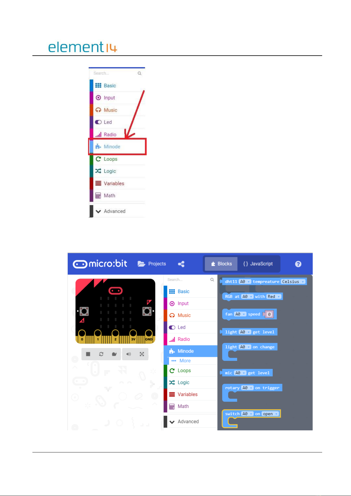
c) After selecting the mi:node library, wait a moment and you will see it being added to your
project. This may take a few seconds.
User Manual V3.1
Element14 | element14.com/minode 10
Image 3.2c –mi:node packed added
Refer to the example code or API reference and drag the library blocks you want to use into
your project space.
Table des matières


