ELBRO SMSB12 Manuel utilisateur

Operating Instructions
SMSB12, Firmware 3.0
SMSB12SW, Version 3.0

SMSB12 / SMSB12SW
2

SMSB12 / SMSB12SW
3
Safety Information
•The SMSB12 device incorporates a latest-generation Quad-band GSM engine. To install and
use it correctly, the indications given in this manual are to be strictly respected.
•The SMSB12 device is a low-power radio transceiving device. When it is operating, it sends
and receives radio frequency energy. Operating the SMSB12 device close to radios, televi-
sions, telephones or electronic devices in general may cause interference. The SMSB12 de-
vice may be subject to interference that affects its performance.
•Do not install the SMSB12 device close to pacemakers, auditory prostheses or medical devices
in general as the SMSB12 device may interfere with the operation of these devices.
•The SMSB12 device must be turned off on aeroplanes. Make sure that the device cannot be
turned on accidentally.
•Do not use the SMSB12 device in the presence of inflammable gases or fumes. Turn off the
device when close to petrol stations, fuel deposits and chemical plants.
•The SMSB12 device operates by means of a radio signal, no mobile telephone operator is ca-
pable of ensuring a connection at all times. For this reason, the SMSB12 device cannot be
used in life support systems.
Notes
•All information contained in this manual is subject to change without prior notice.
•No part of this manual may be reproduced, in any form or by any means, electronic or
physical, or otherwise, including photocopying or storage, for needs other than the per-
sonal use of the user, without the prior written permission by Elbro AG.
•The use, copying, modification, disassembly or transmission of the SMSB12SW software
is forbidden, except for needs specifically authorized under this licence. Unless specifi-
cally authorized, all rights are held by Elbro AG and/or its suppliers.
•All illustrations in this manual refer to version SMSB12SW 1.1 with Windows XP platform.
Unless indicated otherwise, the capabilities of SMSB12SW refer to the XP version.
•Windows 98SE, Windows Me, Windows NT, Windows 2000 and Windows XP refer to
relative trademark registered by Microsoft inc.
•For any other trademark or product cited reference is made to relative owner.

SMSB12 / SMSB12SW
4
Foreword
The SMSB12 device is a latest generation stand-alone GSM remote control provided with two sig-
nalling inputs and an SPDT relay output.
Up to five SMS messages for opening and closing the contact can be associated with each signal-
ling input line.
The SMSB12 device is able to receive commands sent via SMS messages or else through a sim-
ple voice call with zero cost.
The SMSB12 device is provided with specific configuration software that allows considerable sim-
plification of the installation procedure, namely SMSB12SW software. The SMSB12SW software
features a user-friendly graphic interface which guides the user step-by-step through the installation
procedure of the SMSB12 device.

SMSB12 / SMSB12SW
5
Installation
In order to ensure the operator's safety and the correct operation of the SMSB12 device, the device
should be installed exclusively by qualified staff. The rules listed below should also be strictly ob-
served.
Environmental conditions
The SMSB12 device (the instrument and all cables connected to it) should be installed in places ei-
ther free or far from:
•Dust, humidity, great heat;
•Direct exposure to sunlight;
•Objects radiating heat;
•Objects generating a strong electromagnetic field;
•Liquids or corrosive chemical substances.
The SMSB12 device has been designed to operate at a temperature of between -5°C and +45°C
(standard working temperature)
1
.
Avoid sudden changes in temperature and/or humidity.
Degree of Protection
During the installation of the SMSB12 device, the following degree of protection is to be ensured:
•IP40: minimum degree of protection, which must always be guaranteed;
•IP54: protection to be guaranteed when using the device outdoors.
Power supply
Observe the following rules:
•Do not use cables longer than 3 m;
•The external power supply unit (e.g. mains charger), must comply with the EN 60950 Directive
(electrical safety);
•Do not invert the polarity of the power supply cables.
Signalling Inputs
During the installation of the device, strictly observe the indications given in this manual.
Observe the polarities and nameplate data indicated in the manual.
Relay Output
During the installation of the device, strictly observe the indications given in this manual.
Install the external equipment correctly and observe the nameplate data indicated in this manual.
Under no circumstances, exceed the nameplate data.
1
The temperature range indicated refers to standard applications and corresponds to the factory
setting.

Description of the SMSB12 Device
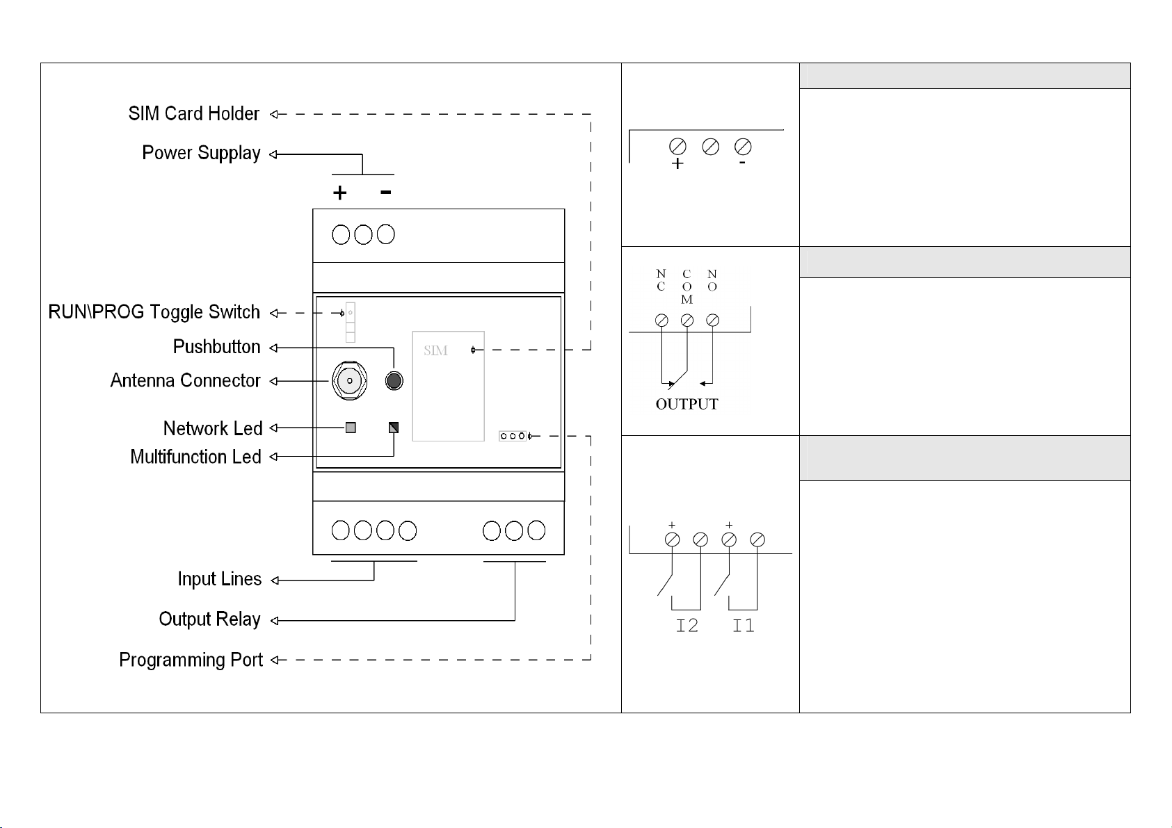
POWER SUPPLY
•12 to 24V DC [Nominal Range];
•9 to 30V DC [Extended Range ]
•I
max
=500mA;
•Never use cables with length exceeding 3m;
BISTABLE RELAY OUTPUT
•Rest position: NC-COM [red Multifunction
LED];
•Rated switching capacity: 10A, 250V
AC;
•Never use cables with length exceeding 3m.
VOLTAGE-FREE CONTACT IN-
PUTS
•It is possible to connect switches such as:
oMechanical and electromechanical with
suitable nameplate data: 5V DC min.
50µA;
oElectronic with suitable nameplate data:
5V DC min. 50µA. Observe the polarity
given alongside.
•Status:
oON : Closed;
oOFF : Open.
•Each input can be associated with up to five
SMS for both ON-OFF transition and OFF-
ON transition.

SMSB12 / SMSB12SW
7
Network LED
The Network LED is able to provide the following information:
LED STATUS DEVICE STATUS
Unlit The device is off
Solid Green
•the SIM card has not been inserted correctly;
•the SIM card is protected by a PIN code;
•the device is not linked to the GSM n
etwork and is in
the network search phase.
Flashing green
The device is linked to the GSM network and is ready to
receive commands
Multifunction LED
The multifunction LED is able to provide the following information:
•relay output status:
oRed LED: contacts on COM-NC,
oGreen LED: contacts on COM-NO.
•Reception Level of the GSM network measured by the device;
•Device in PROG. Mode.
Push button
The push button located on the front panel can be used for:
•Changing the output status of the device;
•Displaying the reception level of the GSM network measured by the device.
RUN\PROG toggle switch
The RUN\PROG switch allows:
oStarting the PROG mode for programming the SMSB12 device;
oEnding the PROG mode and starting the RUN mode after programming the SMSB12 device.
Programming Port
The programming port is used during installation, for connecting the SMSB12 device to a PC and for set-
ting the configuration parameters via the SMSB12SW software.
Input and Output lines
After the programming procedure has ended, the status of the signalling inputs is considered as current
status of the signalling lines.
The device memorizes each variation of the input and output lines. In case of a black-out, when the
power supply is restored, the device gives the output at the last known status and handles any new re-
quests for forwarding signalling SMS messages.

SMSB12 / SMSB12SW
8
Installation of the SMSB12SW Software
SMSB12SW is a software package designed for very easy presetting of the SMSB12 device.
SMSB12SW features a user-friendly graphic interface, allowing easy approach even for the less expert
users.
The following material (contained in the kit) is required for programming the SMSB12 device:
•One cable for RS232 proprietary programming.
•Configuration CD.
Before proceeding to install the software, it is advisable to upgrade your own operating system.
The SMSB12SW installation procedure is as follows:
1. Switch on the computer and start Windows;
2. Insert the Mini-CD in the CD-ROM drive;
3. Wait for the automatic starting of the CD-ROM. If the automatic starting has been disabled, open
Computer Resources (My Computer) and click on the CD-ROM icon with the right mouse button,
then click on Autoplay.
4. Click on the setup icon “Install SMSB12SW”
Caution: during installation of the SMSB12SW software it could be necessary to install Microsoft .NET
Framework 3.5. An internet connection is required.
Before running the program, read the chapters regarding the programming procedure of the SMSB12
device.
Configuration of the SMSB12 device
For correct operation of the SMSB12 device, proceed as follows:
1. start the SMSB12 device in PROG mode;
2. start the SMSB12SW program and connect to the device;
3. enter the configuration parameters through the SMSB12SW software, and download them in the de-
vice;
4. start the RUN mode of the SMSB12 device.
PROG mode
To configure SMSB12 with SMSB12SW software, start the device in programming mode.
Proceed as follows:
1. switch off the SMSB12 device;
2. insert the SIM Card in relative slot;
3. connect the RS232 proprietary data cable to the programming port of the device;
4. connect the RS232 data cable to relative port on the PC.
5. turn the RUN\PROG toggle switch to PROG;
6. switch on the device;
The programming mode is indicated by the green flashing of the multifunction LED.

SMSB12 / SMSB12SW
9
Connection to the device
•Start the SMSB12SW;
•Select the communication (COM) port where to connect the SMSB12 device;
•From the “Connection” menu, select “Connect”;
•
In order to ensure correct operation of the SMSB12 device, connection should be made to the device
only and exclusively during the programming mode.
PIN code
If your SIM card is protected by a PIN code, the SMSB12SW software automatically opens a mask for
entering the PIN code. After entering the code, the mask will be disabled permanently.
System Password
The SMSB12 device is protected by a four-digit password, de-
fined as “system password”.
The system password can be selected freely by the end user;
it must be used each time a command SMS message is sent.
Enter the password in the appropriate field.
Control Panel
The “Control Panel” of the program has three buttons as follows:
•Download Data: serves for importing data from an already programmed device [the device must be in
programming mode];
•Upload Data: allows sending configuration parameters to the device connect to the PC [after entering
the configuration parameters, press this button to make the settings definite];
•Clear Data: Allows deleting all the data contained in the device connected to the PC [the device must
be in programming mode];

SMSB12 / SMSB12SW
10
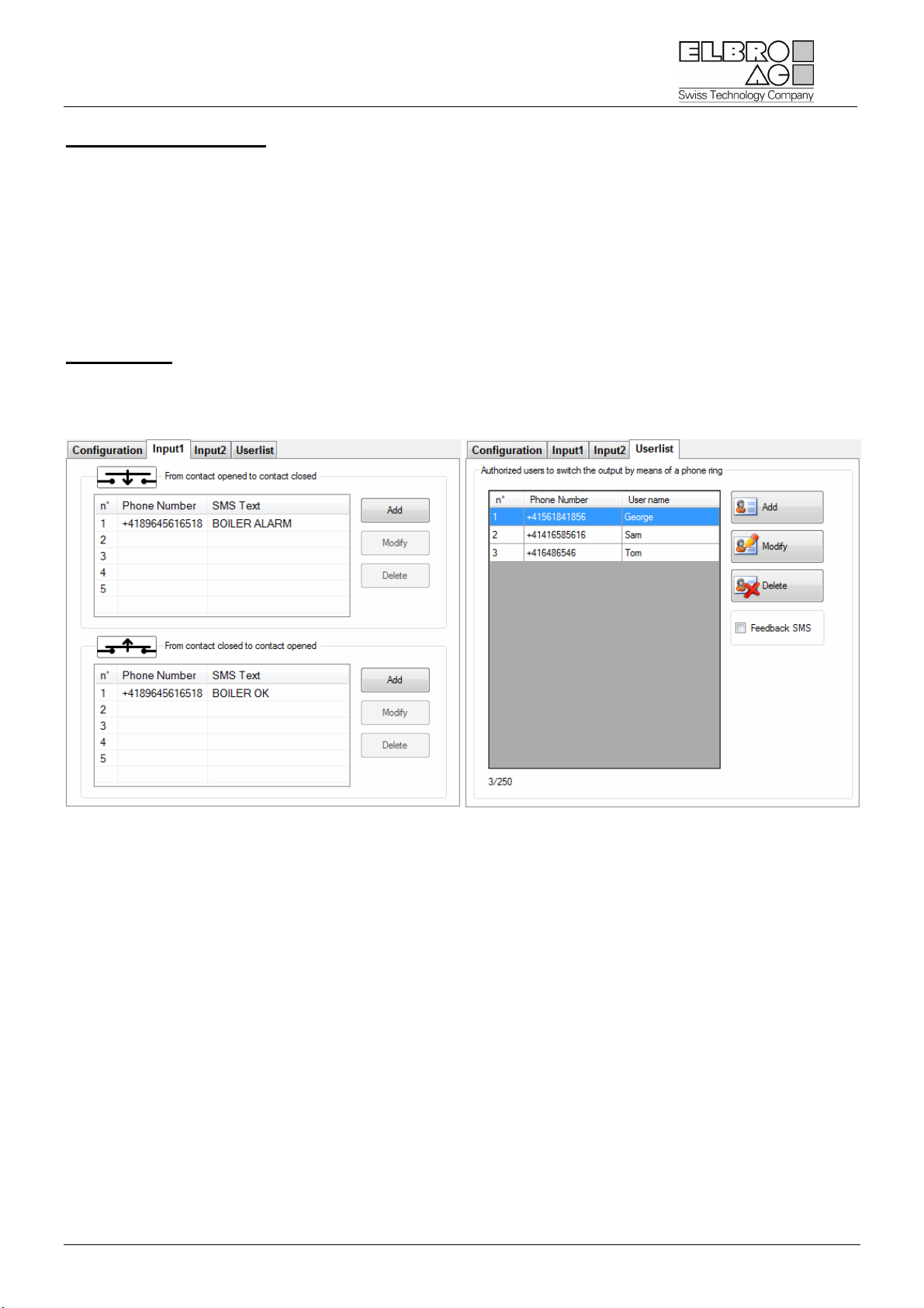
Signalling Inputs
The device is provided with two signalling inputs.
Two events can be associated with each input, namely:
•“closing” event: corresponds to closing the contacts of the signalling line;
•“opening” event: corresponds to opening the contacts of the signalling line.
The end user can associate from a minimum of zero (0) up to a maximum of five (5) SMS messages with
each event.
The end user can choose freely the text of a signalling SMS message (max. length 160 characters) and
the destination.
User List
During programming, it is possible to define users enabled for the voice call (see Voice call chapter). It is
possible to select, if the device, after carrying out the command via a voice call at zero cost, has to send
or not if a feedback SMS to the enabled user that had generate the command.
Ce manuel convient aux modèles suivants
1
Table des matières
Manuels Électricité industrielle populaires d'autres marques

Murata
Murata GJM0335C1E4R4BB01 Series Manuel utilisateur

Stahl
Stahl 8575/12 Manuel utilisateur

SI
SI Pegasus Manuel utilisateur

Murata
Murata GRM1555C1H2R7CA01 Seies Manuel utilisateur

Murata
Murata GRM0225C1E6R4BA03 Series Manuel utilisateur

Cooper Power Systems
Cooper Power Systems VXE15 Manuel utilisateur

S&C
S&C Vista SD Manuel utilisateur

Murata
Murata GRM0335C2A7R3CA01 Series Manuel utilisateur

Siemens
Siemens 3VA9988-0BM10 Manuel utilisateur

Siemens
Siemens SITRANS LVS100 Manuel utilisateur

Murata
Murata GRM32ER60G227ME05 Series Manuel utilisateur

Siemens
Siemens SENTRON SUPERSWITCH 3KL82 Series Manuel utilisateur