MP500 HD Media Player Manual Page 7of 62 Rev. 110
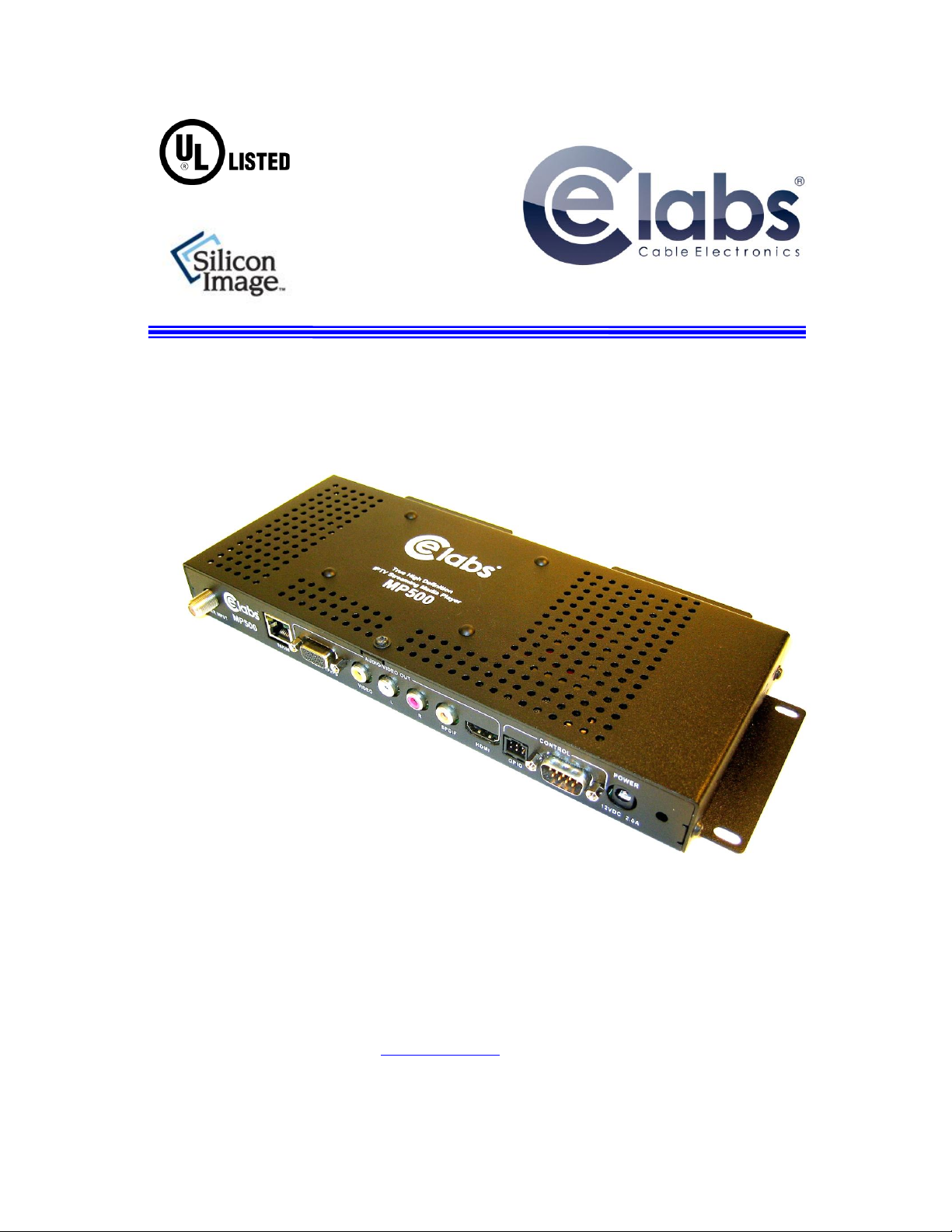
MP500 Connections
The MP500 is capable of driving a wide variety of displays at up to 1080P resolution at bit rates up to 40 Mbps (mpeg2 file
type). Depending upon your application, connect the following cables to operate the unit.
Display cable –Depending on the application, plug in the cable from the media player to the display, switch, or
first distribution amplifier. The HDMI and Component outputs are both active simultaneously.
oThe component video output (for connection to CElabs AV901HD distribution amplifier) uses a DB-15
to RCA cable to break out the video signal. The L/R audio ports can be used in conjunction with the
component or the composite video ports.
oIF the TV wall uses CElabs HDMI distribution amplifiers, connect the HDMI cable.
oIf your application uses an older monitor or if you need to drive a modulator, the composite video port is
always on regardless of the output resolution.
oThe DB-15 VGA/YPrPb port is primarily used for outputting component video. The unit is capable of
outputting VGA signals at various resolutions but only with a simultaneous HDMI connection.
Switching between the HDMI/Component and VGA requires the use of the CElabs QuickSign software
application.
Note: Video output resolution has been pre-set at the factory for 1080i (in most applications) on the HDMI and Component
Video Outputs (unless another resolution is requested). Standard 480i video is available on the composite video port at all
times. The output and resolution can be specified at time of order and pre-set to your requirements.
Audio cable –The analog audio output is via two RCA jacks on the rear panel. Connect a patch cable from the
rear jacks to the display or audio system as desired.
Note: If HDMI cables being used, separate audio cables are not required as long as the monitor has internal
speakers..
SPDIF –Digital PCM Stereo audio is available on the SPDIF RCA connector.
Tuner Input (ATSC Tuner Option on the MP500T) - Connect the F-connector cable from the off-air antenna or
High Definition modulator to the Tuner Input. Tighten the F-connector securely. Ensure the RF level at the input
is greater than -25dBmV (unit mutes @ -30dBmV). The ATSC channel may be changed by remote PC application
or by IR remote control. Press the up or down arrow keys to increase or decrease the channels one at a time. You
may also type in the channel number directly on the remote. Typing the –1, -2, or -3 first is necessary. Example:
To tune to channel 14-1, type 1 then 4 then 1 and press the Enter key.
Power –The MP500 uses a 12VDC, 2A power supply. Total power consumption is approximately 7 Watts which
leaves a large reserve in the power supply. Insert the power supply 12 VDC plug into the MP500 power jack.
Insert the AC Plug of the power supply into an electrical outlet. After a few seconds, the front panel green LED
will light (you may also notice a red LED that is illuminated during the boot process. The red LED will flash
during normal operation).
Please wait for approximately 1 minute until the unit completes the boot-up process. The media player can be
configured to have a default start-up item such as a video file or ATSC RF channel (ATSC option). If the default
startup item has been configured, Video should start playing automatically when the unit has completed its boot-
up process.
IR Remote- The IR remote is used to access the unit’s On Screen Display menu. If you need to determine the IP
address for the unit, go to the network settings window. In certain applications, with channel setting pre-set at the
factory, the infrared remote is not needed. There are applications for the MP500 that use of the remote could be
helpful. Please store the remote in a safe location for possible later use.
GPIO - These ports are generally used to interface with pushbuttons that can be used to trigger certain videos.
Refer to the GPIO section later in this manual for a full description.
RS-232 –The media player may be controlled via the serial port. Refer to the “Using the RS-232 XApp” section.
IR Jack –A remote IR receiver may be plugged into the front panel IR jack. This allows use of the Remote
Control even when the unit may be installed in an enclosure or behind a TV where IR access is difficult.