EGAmaster EgaTronic COD.58515 Manuel utilisateur

MULTIMETER
OPERATING INSTRUCTIONS
GUARANTEE........................ 21
COD.58515

2
OVERVIEW
To avoid electric shock or personal injury, read the “Safety Information” and “Rules for Safety
Operation”carefully before using the Meter.
Digital Multimeters COD.58515 (hereafter referred to as “the Meter”) is 4 1/2 digits
with ex-large LCD, steady operations, fashionable structure and highly reliable hand-held
measuring instrument. The Meter uses large scale of integrated circuit with double integrated
A/D converter as its core and has full range overload protection. The Meter has 28 dierent
measuring functions. It has not only can measure AC/DC Voltage, AC/DC Current, Resistance,
Temperature, Capacitance,
Frequency, Transistor, Diode and Continuity, but also have Data Hold, Full Icon Display,
Overload Protection and Sleep Mode features.
UNPACKING INSPECTION
Open the package case and take out the Meter. Check the following items carefully to see
any missing or damaged part:
Item Description Qty
1 Operating Manual 1 piece
2 Test Lead 1 pair
3 Multi-Purpose Socket 1 piece
4 Point Contact Temperature Probe 1 piece
5 Holster 1 piece
6 9V Battery (NEDA 1604, 6F22 or 009P) 1 piece
In the event you nd any missing or damage, please contact your dealer immediately.
SAFETY INFORMATION
This Meter complies with the standards IEC61010: in pollution degree 2, overvoltage
category (CAT. II 1000V, CAT. III 600V) and double insulation.
CAT. II: Local level, appliance, PORTABLE EQUIPMENT etc., with smaller transient voltage
overvoltages than CAT. III.
ENGLISH

3
CAT. III: Distribution level, xed installation, with smaller transient overvoltages than CAT. IV
Use the Meter only as specied in this operating manual, otherwise the protection provided
by the Meter may be impaired.
In this manual, a Warning identies conditions and actions that pose hazards to the user, or
may damage the Meter or the equipment under test.
A Note identies the information that user should pay attention to.
International electrical symbols used on the Meter and in this Operating Manual are
explained on page 4.
RULES FOR SAFE OPERATION
Warning!
To avoid possible electric shock or personal injury, and to avoid possible damage to
the Meter or to the equipment under test, adhere to the following rules:
• Before using the Meter inspect the case. Do not use the Meter if it is damaged or the
case (or part of the case) is removed. Look for cracks or missing plastic. Pay attention to the
insulation around the connectors.
• Inspect the test leads for damaged insulation or exposed metal. Check the test leads for
continuity. Replace damaged test leads with identical model number or electrical specications
before using the Meter.
• Do not apply more than the rated voltage, as marked on the Meter, between the terminals
or between any terminal and grounding.
• The rotary switch should be placed in the right position and no any changeover of range
shall be made during measurement is conducted to prevent damage of the Meter.
• When the Meter working at an eective voltage over 60V in DC or 30V rms in AC, special
care should be taken for there is danger of electric shock.
• Use the proper terminals, function, and range for your measurements.
• If the value to be measured is unknown, use the maximum measurement position and
reduce the range stop by step until a satisfactory reading is obtained.
• Do not use or store the Meter in an environment of high temperature, humidity, explosive,
inammable and strong magnetic eld. The performance of the Meter may deteriorate after
dampened.
• When using the test leads, keep your ngers behind the nger guards.
• Disconnect circuit power and discharge all high-voltage capacitors before testing
resistance, continuity, diodes, capacitance or current.
• Before measuring current, check the Meter’s fuses and turn o power to the circuit before
connecting the Meter to the circuit.
• Replace the battery as soon as the battery indicator appears. With a low battery, the
Meter might produce false readings that can lead to electric shock and personal injury.
• Remove test leads and multi-purpose socket from the Meter and turn the Meter power o
before opening the Meter case.
• When servicing the Meter, use only the same model number or identical electrical
specications replacement parts.
• The internal circuit of the Meter shall not be altered at will to avoid damage of the Meter
and any accident.

4
• Soft cloth and mild detergent should be used to clean the surface of the Meter when
servicing. No abrasive and solvent should be used to prevent the surface of the Meter from
corrosion, damage and accident.
• The Meter is suitable for indoor use.
• Turn the Meter power o when it is not in use and take out the battery when not using for
a long time.
• Constantly check the battery as it may leak when it has been using for some time,
replace the battery as soon as leaking appears. A leaking battery will damage the Meter.
INTERNATIONAL ELECTRICAL SYMBOLS
AC (Alternating Current)
DC (Direct Current)
Grounding
Double Insulated
Deciency of Built-In Battery.
Warning. Refer to the Operating Manual
Diode
Fuse
Continuity Test
Conforms to Standards of European Union
THE METER STRUCTURE (see gure 1)
1__ LCD Display
2__ HOLD Button.
3__ Rotary Switch
4__ COM Input Terminal
5__ POWER
6__ Other Input Terminal.
7__ mA Input Terminal
8__ 20A Input Terminal
(gure 1)

5
ROTARY SWITCH
Below table indicated for information about the rotary switch positions.
Rotary Switch Position Function
DC voltage measurement
AC voltage measurement
hFE Transistor Test
AAC Current Measurement
DC Current Measurement
Fcx Capacitance Test
ºC Temperature Measurement
Hz Frequency Measurement
Diode test
Continuity test
ΩResistance measurement
FUNCTIONAL BUTTONS
Bellow table indicated for information about the functional button operations.
Button Operation Performed
Yellow Button
Turn the Meter on and o.
- Press down the POWER to turn on the Meter.
- Press up the POWER to turn o the Meter.
HOLD
Blue Button
-Press HOLD once to enter hold mode.
- Press HOLD again to exit hold mode.
- In Hold mode, is displayed and the present value is shown.
DISPLAY SYMBOLS (see gure 2)
(gure 2)

6
Nº Symbol Meaning
1
The battery is low.
Warning: To avoid false readings, replace the
battery as soon as the battery indicator
appears.
2 Warning Symbol
3AC Indicator for AC voltage or current.
The displayed value is the mean value.
4 Indicates negative reading
5 Test of diode
6The continuity buzzer is on
7 Date hold is active
8
Connect Terminal
Indicator of connecting test leads into dierent input
terminals.
9hFE The Unit of Transistor Test
10
mV, V V: Volts. The unit of voltage.
mV: Millivolt. 1 x 10⁻³ or 0.001 volts
Ω, kΩ, MG
Ω: Ohm. The unit of resistance
kΩ: kilohm. 1 x 10³or 1000 ohms
MΩ: Megaohm. 1 x 10⁶or 1.000.000 ohms.
µA,mA, A
A: Amperes (amps). The unit of current.
mA: Millliamp. 1 x 10⁻³ or 0.001 amperes.
µA: Microamp. 1x 10⁻⁶ or 0.000001 amperes.
ºC, ºF ºC: Centigrade temperature
ºF: Fahrenheit temperature
kHz Hertz. The unit of frequency in cycles/second.
Kilohertz. 1 x 10³ or 1.000 hertz.
F, nF, µF
F: Farad. The unit of capacitance.
µF: Microfarad. 1 x 10⁻⁶ or 0.000001 farads.
nF: Nanofarad. 1 x 10⁻⁹ or 0.000000001 farads.
7
MEASUREMENT OPERATION
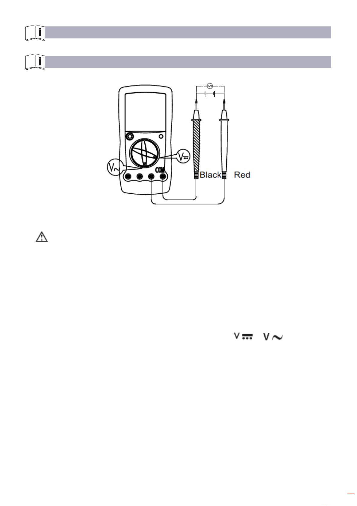
A. DC AND AC VOLTAGE MEASUREMENT (see gure 3)
(gure 3)
Warning!
To avoid harms to you or damages to the Meter from electric shock, never attempt to
measure voltages higher than 1000 or 1000V rms although readings may be obtained.
The DC Voltage ranges are: 200mV 2V, 20V, 200V and 1000V.
The AC Voltage ranges are: 2V, 20V, 200V and 1000V.
To measure DC Voltage, connect the Meter as follows:
1. Insert the red test lead into the VΩ input terminal and the black test lead into the COM
input terminal.
2. Set de rotary switch to an appropiate measurement position in or range.
3. Connect the test leads parallel across with the object to be measured.
The measured value shows on the display.
Note
• If de value of voltage to be measured is unknown, use the maximum measurement
position (1000V) and reduce the range step by step until a satisfactory reding is obtained.
• The LCD displays “1” indicating the existing selected range is overloaded , it is required
to select a higher range in order to obtain a correct reading.
• In each range, the Meter has an input impedance of approx. 10MΩ this loading eect can
cause measurement errors in high impedance circuits. If the circuit impedance is less than or
equal to 10kΩ the error is negligible (0.1% or less).
• When DC voltage measurement has been completed, disconnect the connection
between the testing leads and the circuit under test, and remove the testing leads away from the
input terminal of the Meter.

8
B. DC AND AC CURRENT MEASUREMENT (see gure 4)
(gure 4)
Warning!
Never attempt an in-circuit current measurement where the open circuit voltage
between terminals and ground is greater than 60V DC or 30V rms in AC.
If the fuse burns out during measurement, the Meter may be damaged or the operator
himself may be hurt. Use proper terminals, function, and range for the measurement.
When the testing leads are connected to the current terminals, do not parallel them
across any circuit.
The DC Current Measurement has 3 measurement positions on the rotary switch: 2mA,
200mA and 20A.
The AC Current Measurement has 3 measurement positions on the rotary switch: 20mA,
200mA and 20A.
To measure current, do the following:
1. Turn o power to the circuit. Discharge all high-voltage capacitors.
2. Insert the red test lead into the 20A or mA input terminal and the black test lead into the COM
terminal.
When you measure current below 200mA, please insert the red test lead into the mA input
terminal. When you measure 200mA or above, insert the red test lead into the 20A input
terminal.
3. Set the rotary switch to an appropriate measurement position in or range.
4. Break the current path to be tested. Connect the red test lead in serial to the more positive
side of the break and the black test lead to the more negative side of the break.
5. Turn on power to the circuit.
The measured value shows on the display.

9
Note
• l If the value of current to be measured is unknown, use the maximum measurement
position, and reduce the range step by step until a satisfactory reading is obtained.
• l For safety sake, the measuring time for high current should be less than 10 seconds
and the interval time between 2 measurements should be greater than 15 minutes.
• l When current measurement has been completed, disconnect the connection between
the testing leads and the circuit under test, and remove the testing leads away from the input
terminal of the Meter.
C. MEASURING RESISTANCE (see gure 5)
(gure 5)
Warning!
To avoid damages to the Meter or to the devices under test, disconnect circuit power
and discharge all the high-voltage capacitors before measuring resistance.
The resistance ranges are: 200Ω, 2kΩ, 20kΩ, 2MΩ and 200MΩ.
To measure resistance, connect the Meter as follows:
1. Insert the red test lead into the VΩ input terminal and the black test lead into the COM
terminal.
2. Set the rotary swich to an appropriate measurement position in Ωrange.
3. Connect the test leads parallel across with the object being measured.
Note
• The test leads can add 0.1Ω to 0.3 of error to the slow-resistance (200Ω) measurement.
• For high resistance (>1MΩ), it is normal taking several seconds to obtain a stable
reading.
• When there is no input, for example in open circuit condition, the Meter displays “1”.
• When resistance measurement has been completed, disconnect the connection between
the testing leads and the circuit under test, and remove the testing leads away from the input
terminal of the Meter.

10
D. MEASURING DIODES AND CONTINUITY (see gure 6)
(gure 6)
Warning!
To avoid damage to the Meter or to the equipement under test, disconnect circuit
porwer and discharge all high-voltage capacitors bere measuring diodes.
To avoid harms to you, never attempt to input voltages higher than 60V DC or 30V rms
in AC.
Measuring Diodes:
Use the diode test to check diodes, transistors, and other semiconductor devices. The diode
test sends a current through the semiconductor junction, and then measures the voltage drop
across the junction. A good silicon junction drops between 0.5V and 0.8V.
To test out a diode out of a circuit, connect the Meter as follows:
1. Insert the red test lead into the VΩ input terminal and the black test lead into the COM
terminal.
2. Set the rotary swich to .
3. For forward voltage drop readings on any semiconductor component, place the red test lead
on the component’s anode and place the black test lead on the component’s cathode.
The measured value shows on the display.
Note
• In a circuit, a good diode should still produce a forward voltage drop reading of 0.5V to
0.8V; however; the reverse voltage drop reading can vary depending on the resistance of other
pathways between the probe tips.
• Connect the test leads to the proper terminals as said above to avoid error display. The
LCD will display “1” indicating open-circuit for wrong connection. The unit of diode is Volt (V),
displaying the positive-connection voltage-drop value.
• The open-circuit voltage is around 3V.
• When diode testing has been completed, disconnect the connection between the testing
leads and the circuit under test, and remove the testing leads away from the input terminal of
the Meter.
Table des matières
Autres manuels EGAmaster Multimètre

EGAmaster
EGAmaster 51643 Manuel utilisateur

EGAmaster
EGAmaster 51267 Manuel utilisateur

EGAmaster
EGAmaster EGAtronik 51255 Manuel utilisateur

EGAmaster
EGAmaster EGATRONIK Manuel utilisateur

EGAmaster
EGAmaster EGA TRONIK 51252 Manuel utilisateur

EGAmaster
EGAmaster egatronic 51259 Manuel utilisateur

EGAmaster
EGAmaster EGAtronik 51253 Manuel utilisateur
Manuels Multimètre populaires d'autres marques


Gossen MetraWatt
Gossen MetraWatt METRAmax 6 Manuel utilisateur

PeakTech
PeakTech 4000 Manuel d'utilisation et d'entretien

YOKOGAWA
YOKOGAWA 90050B Manuel utilisateur

Gossen MetraWatt
Gossen MetraWatt METRALINE DMM16 Manuel utilisateur

Fluke
Fluke 8846A Manuel d'utilisation et d'entretien

Tempo Communications
Tempo Communications MM200 Manuel utilisateur


