Effekta KS5 Series Manuel utilisateur

Grid-Connected Inverter
Installation and Operation Manual
KS5-Series
3000ST / 5000DT
202111 Ver:1.0

User Manual
2
Contents
1.Introduction ....................................................................................................................3
1.1 Product Description .....................................................................................3
1.2 Packaging ...................................................................................................4
1.3 Optional Packaging .....................................................................................4
1.4 Inverter Storage...........................................................................................5
2. Safety Instructions ...........................................................................................................5
2.1 Safety Symbols.......................................................................................................5
2.2 General Safety Instructions.....................................................................................6
2.3 Notice for Use.........................................................................................................7
3. Overview .........................................................................................................................8
3.1 Front Panel Display ................................................................................................8
3.2 LED Status Indicator Light ......................................................................................8
3.3 Keypad (Optional)...................................................................................................8
3.4 LCD (Optional)........................................................................................................9
4. Installation .....................................................................................................................10
4.1 Select a Location for the Inverter ..........................................................................10
4.2 Mounting the Inverter............................................................................................12
4.3 Electrical Connections ..........................................................................................14
4.3.1 Connect PV side of inverter ........................................................................14
4.3.2 Connection of AC output.............................................................................17
4.3.3 External ground connection ........................................................................19
4.3.4 Max, over current protection device (OCPD)...............................................20
4.3.5 Inverter monitoring connection....................................................................21
4.3.6 CT connections (optional) ...........................................................................22
4.3.7 DRED port connections (optional)...............................................................23
5. Start & Stop...................................................................................................................24
5.1 Start the Inverter...................................................................................................24
5.2 Stop the Inverter ...................................................................................................24
6.Operation........................................................................................................................25
6.1 Setup-Technicians Only ........................................................................................26
6.1.1 Set Date/Time.............................................................................................27
6.2 Inquire ..................................................................................................................27
6.3 Statistics...............................................................................................................27
7. Maintenance..................................................................................................................28
8.Trouble shooting.............................................................................................................29
9. Specifications ................................................................................................................32
Inverter Technical Parameter Table -1.........................................................................32
Inverter Technical Parameter Table -2.........................................................................33
10. Quality Assurance........................................................................................................34
User Manual
3
1.Introduction
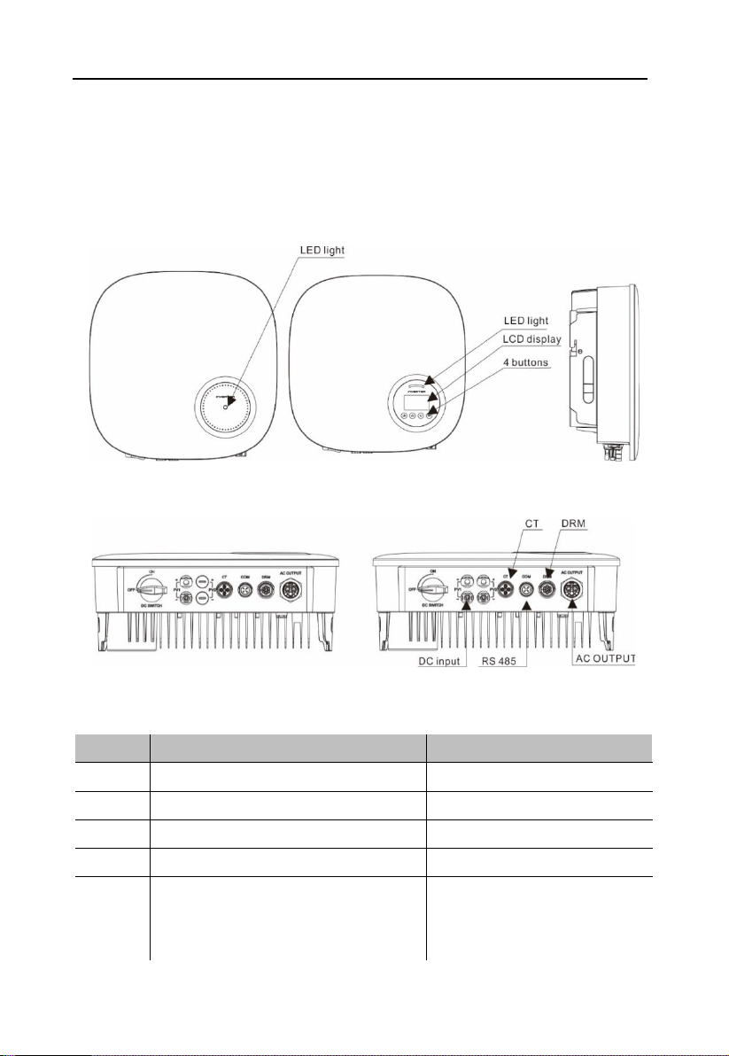
1.1 Product Description
KS5 series single phase inverters integrate DRM and backflow power control function, that
could suitable for smart grid requirement.
LCD display is Optional
Figure 1.2a Bottom side view Figure 1.2b Bottom side view (others)
Object
Description
DVC class
1
PV1, PV2
DVC C
2
AC OUTPUT
DVC C
3
DRM
DVC A
4
CT
DVC A
5
COM
DVC A
User Manual
4
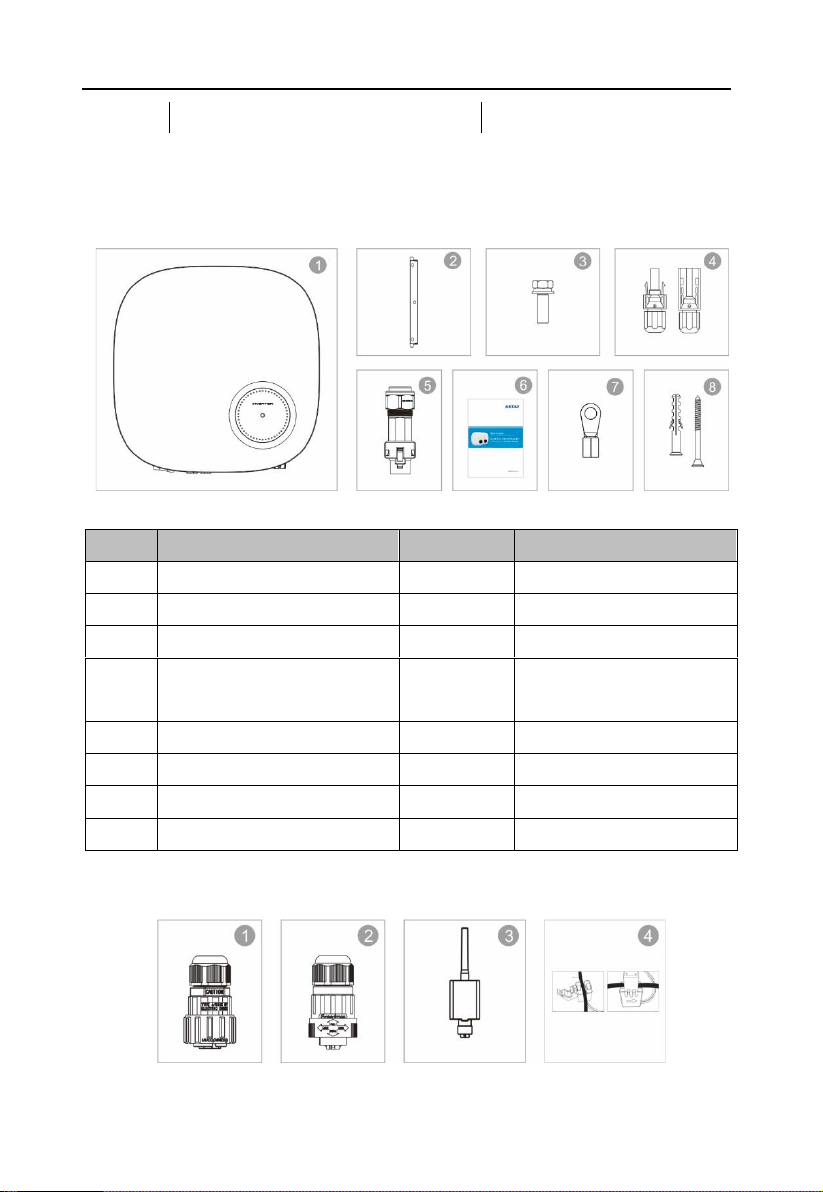
1.2 Packaging
When you receive the inverter, ensure that all the parts listed below are included:
Object
Description
Model
Number
1
PV grid tie inverter
1
2
Wall/pole bracket
3
Locking screws
2
4
DC connector
1 pair for KS5 3000ST,
2 pairs for others
5
AC connector
1
6
Manual
1
7
OT terminal
6
8
Explpsion-proof screws
3/3
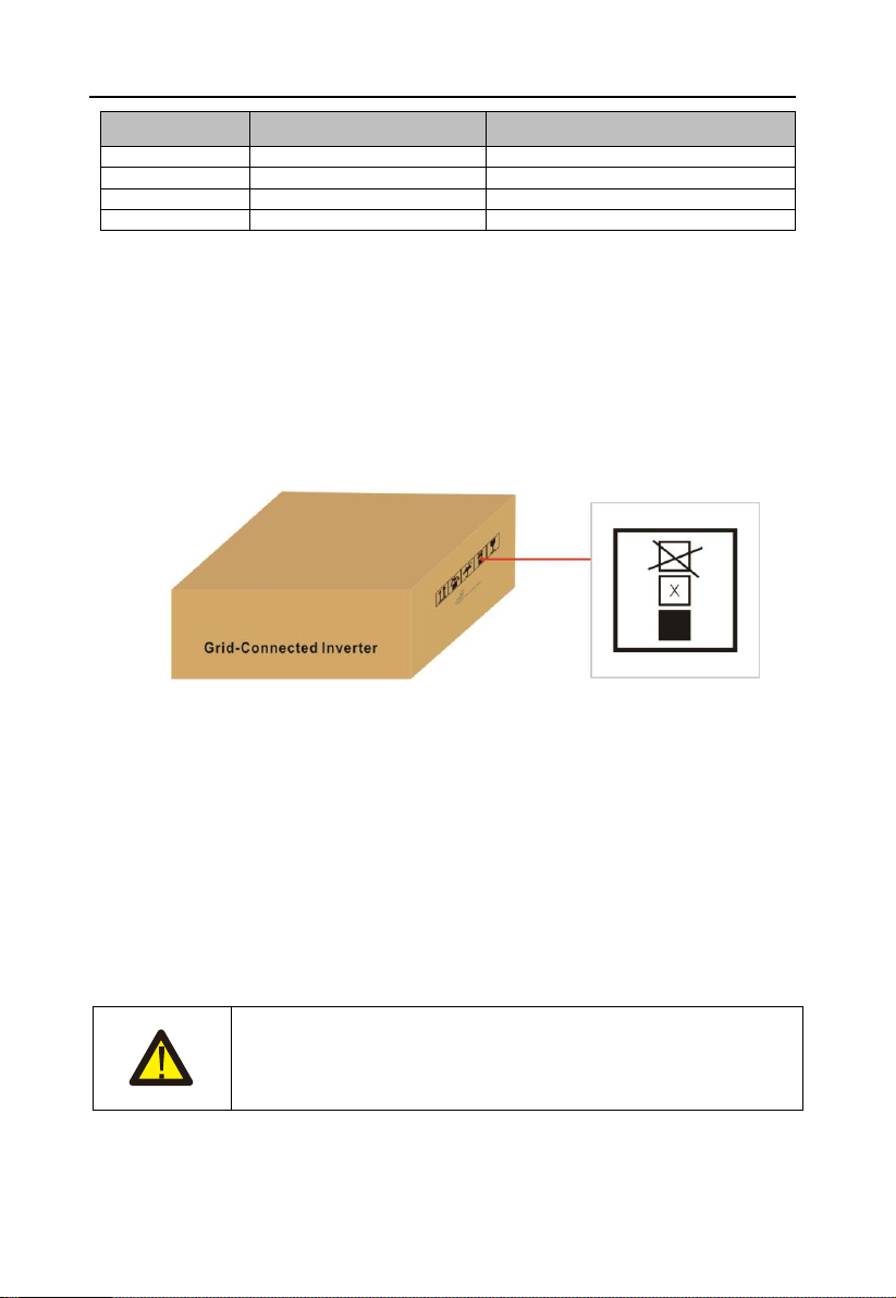
1.3 Optional Packaging
User Manual
5
Object
Description
Number
1
DRM connector
1
2
CT connector
1
3
WiFi/GPRS Stick
1
4
1xCT and com cable
1
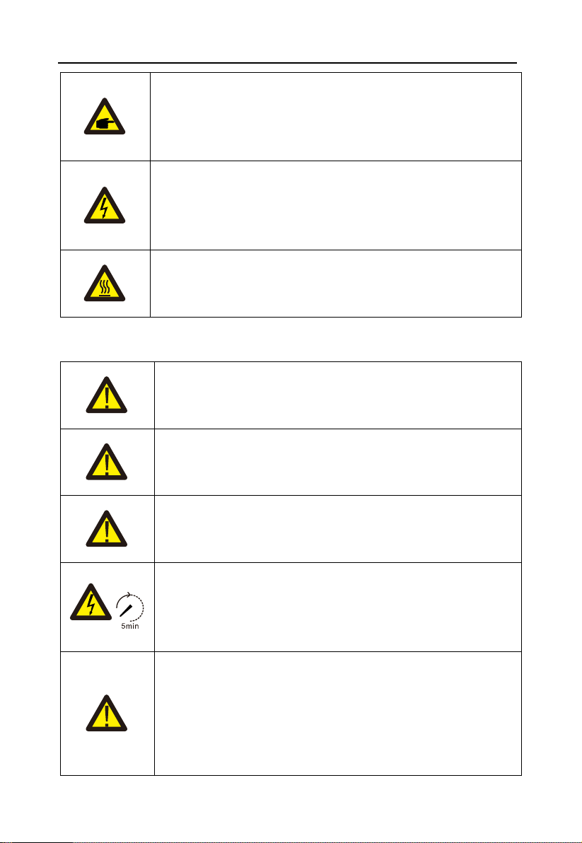
1.4 Inverter Storage
Proper storage is required if the inverter is not installed immediately.
• Store the inverter in the original packing case.
• The storage temperature must be always between -40° C and +70° C, and the storage
relative humidity must be always between 0 and 95%, non-condensing.
• In case of stacking storage, the number of stacking layers should never exceed the limit
marked on the outer side of the packing case.
• The packing case should be upright.
• If the inverter has been stored more than half a year, the qualified personnel should
thoroughly check and test it before using.
2. Safety Instructions
Improper use may result in potential electric shock hazards or burns. This manual contains
important instructions that should be followed during installation and maintenance. Please
read these instructions carefully before use and keep them for future reference.
Contact the nearest hazardous waste disposal station when the products or components are
discarded.
2.1 Safety Symbols
Safety symbols used in this manual, which highlight potential safety risks and important safety
information, are listed as follows:
WARNING:
WARNING symbol indicates important safety instructions, which if not
correctly followed, could result in serious injury or death.
User Manual
6
NOTE:
NOTE symbol indicates important safety instructions, which if not
correctly followed, could result in some damage or the destruction of
the inverter.
CAUTION:
CAUTION, RISK OF ELECTRIC SHOCK symbol indicates important
safety instructions, which if not correctly followed, could result in
electric shock.
CAUTION:
CAUTION, HOT SURFACE symbol indicates safety instructions, which
if not correctly followed, could result in burns.
2.2 General Safety Instructions
WARNING:
Only devices in compliance with SELV (EN 69050) may be connected
to the RS485 and USB interfaces.
WARNING:
Please don't connect PV array positive(+) or negative(-) to ground, it
could cause serious damage to the inverter.
WARNING:
Electrical installations must be done in accordance with the local and
national electrical safety standards.
WARNING:
Do not touch any inner live parts until 5 minutes after disconnection
from the utility grid and the PV input.
WARNING:
To reduce the risk of fire, over-current protective devices (OCPD) are
required for circuits connected to the Inverter.
The DC OCPD shall be installed per local requirements. All
photovoltaic source and output circuit conductors shall have
disconnects that comply with the NEC Article 690, Part II.
User Manual
7
CAUTION:
Risk of electric shock. Do not remove cover. There is no user
serviceable parts inside. Refer servicing to qualified and accredited
service technicians.
CAUTION:
The PV array (Solar panels) supplies a DC voltage when they are
exposed to sunlight.
PV module used with inverter must have an IEC 61730 Class A rating.
2.3 Notice for Use
The inverter has been constructed according to the applicable safety and technical guidelines.
Use the inverter in installations that meet the following specifications ONLY:
1. Permanent installation is required.
2. The electrical installation must meet all the applicable regulations and standards.
3. The inverter must be installed according to the instructions stated in this manual.
4. The inverter must be installed according to the correct technical specifications.
5. To startup the inverter, the Grid Supply Main Switch (AC) must be switched on, before the
solar panel's DC isolator shall be switched on. To stop the inverter, the Grid Supply Main
Switch (AC) must be switched off before the solar panel's DC isolator shall be switched off.

User Manual
8
3. Overview
3.1 Front Panel Display
LCD display is Optional.
Figure 3.1 Front Panel Display
3.2 LED Status Indicator Light
The LED status indicator can display red and green. When the indicator light is on, it indicates
that there is power. When the indicator light is red, it indicates the alarm state; when the
indicator light is green, it indicates the operation state.
Light
Status
Description
ALARM
ON
Alarm or fault condition is detected.
OPERATION
ON
The inverter is operating properly.
FLASHING
Grid Connected countdown
Table 3.1 Status Indicator Light
3.3 Keypad (Optional)
There are four keys in the front panel of the Inverter from left to right: ESC, UP, DOWN and
ENTER keys. The keypad is used for:
• Scrolling through the displayed options (the UP and DOWN keys);

User Manual
9
• Access to modify the adjustable settings (the ESC and ENTER keys).
3.4 LCD (Optional)
The four-line Liquid Crystal Display (LCD) is located on the front panel of the Inverter, which
shows the following information:
• Inverter operation status and data;
• Service messages for operator;
• Alarm messages and fault indications.
You can also get information via WiFi / GPRS.
User Manual
10
4. Installation
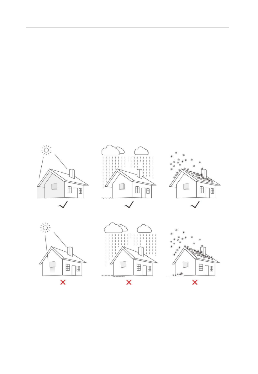
4.1 Select a Location for the Inverter
To selects location for the inverter, the following criteria should be considered:
• Do not install in small closed spaces where air can not circulate freely. To avoid
overheating , always make sure the flow of air around the inverter is not blocked.
• Exposure to direct sunlight will increase the operational temperature of the inverter and
may cause output power limiting. EFFEKTA recommends inverter installed to avoid direct
sunlight or raining.
• To avoid overheating ambient air temperature must be considered when choosing the
inverter installation location. EFFEKTA recommends using a sun shade minimizing direct
sunlight when the ambient air temperature around the unit exceeds 104°F/40°C.
Figure4.1 Recommended Installation locations
• Install on a wall or strong structure capable of bearing the weight.
• Install vertically with a maximum incline of +/-5° . If the mounted inverter is tilted to an
angle greater than the maximum noted, heat dissipation can be inhibited, and may result in
less than expected output power.
• When 1 or more inverters are installed in one location, a minimum 300mm clearance should
be kept between each inverter or other object(if a canopy is added, a distance of 50cm must
Ce manuel convient aux modèles suivants
2
Table des matières
Autres manuels Effekta Onduleur


