After you’ve locked the mount and the CS/CTS device is
in place on your windshield, sit back in your drivers seat
and make sure the viewing angle is as desired. Check
to make sure the device doesn’t create a blind spot that
may impair your view of the road/trac/pedestri-
ans from the drivers seat.
After positioning the device
and the mount, remove any
slack in the OBDII cable and
coil it behind the side panel
you removed earlier. Use the
supplied zip ties to secure the
coiled cable from moving or
falling down under the dash, or
interfering with pedal operation.
Replace all panels removed during
installation
For Operating Instructions and trouble shooting please refer to the User Guide found
in the folder packet that came with your CS or CTS package. For additional questions
not found in the User Guide you can call:
Edge Products Technical Support
Hours Mon-Friday
8:00 a.m. - 5:00 p.m. Mountain Standard Time
1-888-360-EDGE (3343)
Multiple accessories are available for
the CS/CTS device. Accessories
include EGT sensors, back-up
camera, and vehicle-specic
custom mounting solutions.
For more information and
pricing please visit
VIDEO IN PORT (CTS ONLY)
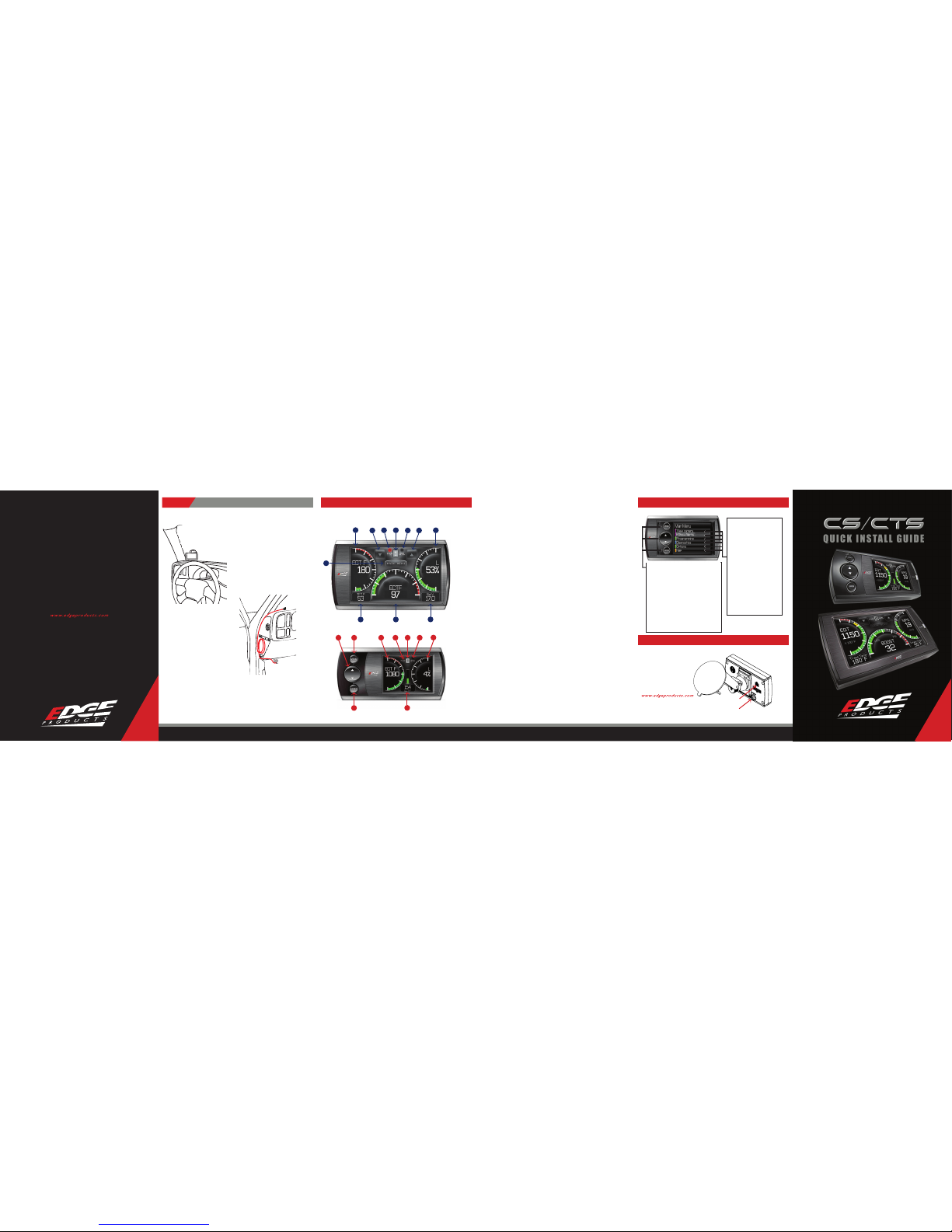
CS/CTS DEVICE DESCRIPTIONS
Step 6:Verify Position and Viewing Placement
ACCESSORIESPORT
*Note: Some states prohibit mounting devices
that may obstruct your view. Please check local
and state laws to ensure compliance.
For alternate mounting options visit
www.edgeproducts.com or www.arkon.com
CTS LAYOUT
CS LAYOUT
Up/Down Arrow Button1. - On the JUICE ATTITUDE these buttons are used to toggle the power level up/
down. On the EVOLUTION,INSIGHT and MILEAGE MAX these buttons may be used for future feature enhance-
ments. In the menus these buttons areused to toggle through the menu items and increase or decrease
values.
Menu Button2. - The menu button gives you access to the main menu.
Left Gauge3. - The left gauge is one of two analog style gauges. The displayed parameterfor all gauges
can be changed by pressing the enter button, choosing the desired gauge, and selecting a dierent parameter
from the drop down list.
Alert Indicator4. - The alert indicator light will illuminate (red) when an alert limit is exceeded. When this
light contains an “R,”it indicates that your Diesel Particulate Filter (DPF) equipped vehicle is performing a
regeneration cycle.
Power Level Indicator5. - The power level indicator represents the current powerlevel. 0 represents
stock.
Backdown Indicator6. - (Juice/Attitude only) The backdown indicator light will illuminate (yellow)
when the Juice module is decreasing power added by the device while exceedinga backdown limit. The light
will contain one of the following characters; E= EGT, S = Transmission Slip, C = Cold Engine.
Right Gauge7. - The right gauge is one of two analog style gauges.
Enter Button8. - The enter button when pressed from the main screen will allow you to change the gauge
parameters. Inthe menus it allows you to select the highlighted option.
Center Gauge9. - The center gauge is a bar style gauge.
Main Menu button1. - The main menu button gives you access to the main menu.
Left Gauge2. - The left gauge is one of three analog style gauges. The displayed parameterfor all gauges
can be changed by simply touching the gauge and choosing a dierent parameter from the drop downlist.
Power level up/down Arrows3. - On the JUICE ATTITUDE these buttons are used to toggle the power
level up/down. On the EVOLUTION,INSIGHT and MILEAGE MAX these buttons may be used for future feature
enhancements.
Alert Indicator4. - The alert indicator light will illuminate (red) when an alert limit is exceeded. When this
light contains an “R,”it indicates that your Diesel Particulate Filter (DPF) equipped vehicle is performing a
regeneration cycle.
Power Level Indicator5. - The power level indicator represents the current powerlevel. 0 represents
stock.
Backdown Indicator6. - (Juice/Attitude only) The backdown indicator light will illuminate (yellow)
when the Juice module is decreasing power added by the device while exceedinga backdown limit. The light
will contain one of the following characters; E = EGT,S = Transmission Slip, C = Cold Engine.
Right Gauge7. - The right gauge is one of three analog style gauges.
Lower Left Gauge8. - The Lower LeftG auge is one of two digital gauges.
Center Gauge9. - The Center gauge is one of three analog style gauges.
Lower Right Gauge10. -The Lower Right Gauge is the second of two digital gauges.
654
9
2
8
1
53
10
3
2
8
1
9
7
6
4
7
3
THE MAIN MENU CONSISTS
OF SIX OPTIONS:
Show alerts -• This item shows the
alert grid screen. *NOTE: This menu
only appears when there is an alert
active
Programming -• This allows you
to program the vehicle to one of the
pre-tuned levels included with the
Mileage Max or Evolution. This menu
item may not be present on certain
products.
Diagnostics -• Thisgives you the
ability to retrieve and clear trouble
codes, as well as other diagnostic
functions depending on vehicle.
Options -• This gives you access
to multiple device settings (i.e.
alert settings, sound duration,
backlight-autodim etc).
Help -• This is used to display product
information, vehicle information,
technical support tools, and contact
information.
MENU NAVIGATION BUTTONS
Both the CS and CTS devices provide you with the
following three buttons for navigating the menu
system:
Menu: The Menu button allows you to enter the main menu
(CS only). Once you are in the menu system you’lluse the Menu
button to return to the previous screen.
UP/Down Arrow: The Up/Down Arrow buttons will allow
you to toggle up or down through the menu options. Each
option will be highlighted as you toggle.
Enter: Pressing the Enter button will select the currently
highlighted option.
*Note: With the CTS device you can simply touch the option
you’dlike to select on the menu screen. As a touch screen
device it will automatically select the option you’ve touched
and advance you to the selected option screen.
CS/CTS MAIN MENU
CS/CTS ACCESSORIES