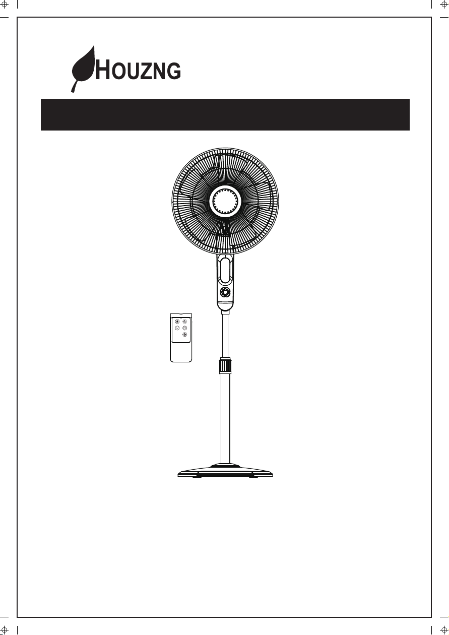
ECOHOUZING FS40-13VR Manuel utilisateur

1
OSCILLATING PEDESTAL FAN
WITH REMOTE CONTROL
Model# FS40-13VR (Item #CT4003L )
READ AND SAVE THESE INSTRUCTIONS
OWNER’S MANUAL
E
c
FS40-13VR-manual-EN+FR 20160217

2
1. Fan should be used under rated voltage.
2. Connect power only after the fan is fully assembled.
3. Never insert fingers, pencils, or any other objects through the grille when the
fan is running.
4. Unplug fan before cleaning or moving.
5. Unplug the fan when removing grilles for cleaning.
6. Be sure the fan is on a stable surface
when operating to prevent the fan from
tipping over.
7. DO NOT use the fan in window. Rain
may create electrical hazard.
1. To reduce the risk of fire or electric shock, do not use this fan with any solid-state
speed control device.
2. DO NOT use fan in window. Rain may create an electrical hazard. Do not leave
the fan operating adjacent to an area where water has collected to avoid the
potential of electrical hazard. Do not immerse unit, plug or cord in water or spray
with liquids.
3. Do not leave the fan running unattended.
4. Please make sure the voltage of the power supply is the same as shown on the
fan nameplate.
5. The remote control must only be used with this fan.
WARNING
PART FIGURE
RULES FOR SAFE OPERATION
Read Rules for Safe Operation and Instructions Carefully.
CAUTION
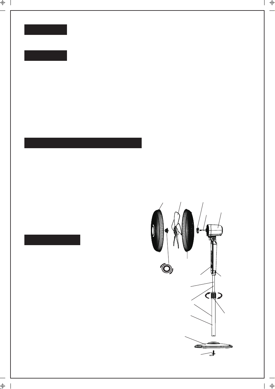
Fastening bolt
Round Base
Tighten
Tighten
Loosen
Touch key
Spinner
Pole assembly
Extension Pole
Internal Pole
Fan Blade Plastic nut
Rear Grille
Motor
shaft Motor Housing
Front Grille
Thumb Screw
Height
adjustment ring

3
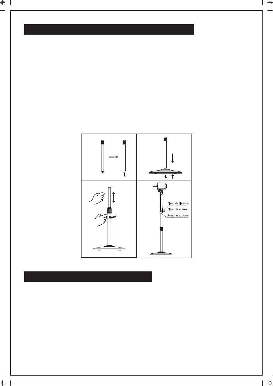
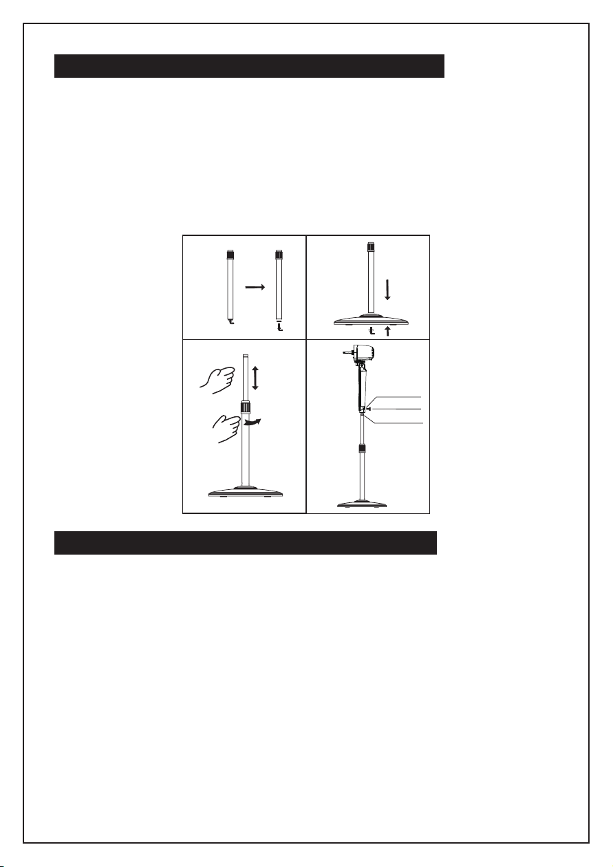
1. Unpack the packing box and take the base & the pole assembly out of the box,
and then loosen the fastening bolt from the bottom of the pole assembly .
(See Fig.1)
2. Put the pole assembly into the Round Base and then lock them together by
tightening the fastening bolt . (See Fig.2)
3. Loosen and remove the height adjustment ring from the extension pole and then
adjust the internal pole to desired height . (NOTE: The internal pole is located
inside the extension pole. If you can't find it , you can pull it out from the
extension pole.) (See Fig.3)
4. Loosen the thumb screw on the bottom of the head unit and attach the head unit
to the column , tighten the thumb screw in alignment with the groove on the
internal pole . (See Fig.4)
ROUND BASE AND COLUMN UNIT ASSEMBLY
GUARD & FAN BLADE ASSEMBLY
1. Remove the plastic nut by turning it counterclockwise.
2. Place the rear guard to the head unit make sure the handle is upward.
3. Screw on the plastic nut (clockwise) securing the fan guard on the head unit.
(Step 1,2,3 see Fig. 5)
4. Discard the small plastic sleeve located on the motor shaft.
5. Install the fan blade onto the motor shaft. Make sure the fan blade slot fits into the
retaining pin of the motor shaft.
6. Attach the spinner to the motor shaft by turning it counterclockwise to secure the
fan blade. (Step 4,5,6 see Fig. 6)
Annulargroove
Trou de fixation
Thumb screw
Loosen
Fig. 1 Fig. 2
Fig. 3 Fig. 4

4
7. Mount the front guard and join both guards together using the clips.
(Step 7 see Fig. 7)
OPERATING INSTRUCTIONS
On the control panel , there are five keys to operate
the fan . (See Fig.8)
- Power Key
Once plugged in, pressing this key will turn the fan on, and
pressing it again will turn the fan off.
- Wind Speed Key
When the fan starts, pressing this key will change
the wind speed in the order of "1-2-3-4-5-6."
- Wind Mode Key
This key is provided to select air supply mode,
and if it is pressed repeatedly, wind type will
change cyclically in the sequence of "Normal
wind - Natural wind - Sleep wind - Smart wind".
A corresponding indicator on the screen will
display the current fan mode. The four wind
modes have the following features:
Normal wind: The fan will deliver wind constantly according to the wind speed level
set by the wind speed key. There are six speeds.
Natural wind: The fan will simulate natural wind
according to the pre-set program, and the delivered wind speed will change based
on the program, making users feel fresh and natural. There are three speeds.
Sleep wind: The fan will simulate natural wind according to the pre-set program with
three wind speeds. The delivered wind is light and soft.
Smart wind: Based on current fan speed and room temperature when this mode is
selected, the fan speed can automatically increase or decrease one setting if room
temperature increase or decrease 0.5℃, until maximum or minimum fan speed
achieved.
Clip
I. CONTROL PANEL
TOUCH KEY
Timer Wind Mode
OscillationWind Speed
ON / OFF
DISPLAY
Sleep wind
Normal wind
6 speed setting
8 hours timer
Natural wind
Oscillating Smart wind
Fig. 8
Fig. 5 Fig. 6 Fig. 7

5
When room temperature falls below 20℃, the fan will stop running and the "Smart"
icon in the display area will keep flashing, once room temperature reaches or
surpasses 20℃, the fan will automatically resume running.
CAUTION: These are features designed for your comfort. They are not a
malfunction.
-OSC key
Press this key to oscillate the fan left and right and corresponding indication is
showed on the control panel . To stop the fan from oscillating in the position
desired , press this key again.
-TIMER key
Press this key repeatedly to set the fan to automatically shut off after a selected
number of hours in the sequence of "1-2-4-8." Don't press this key if you want the
fan to run continuously.
After the timer is set, the timer display will indicate in how many hours the fan will
shut off, in the sequence of "8-4-2-1." For example, if you set timer for eight hours,
after one hour, the display will still indicate "8h," however, after four hours, the
display will change to "4h," etc.
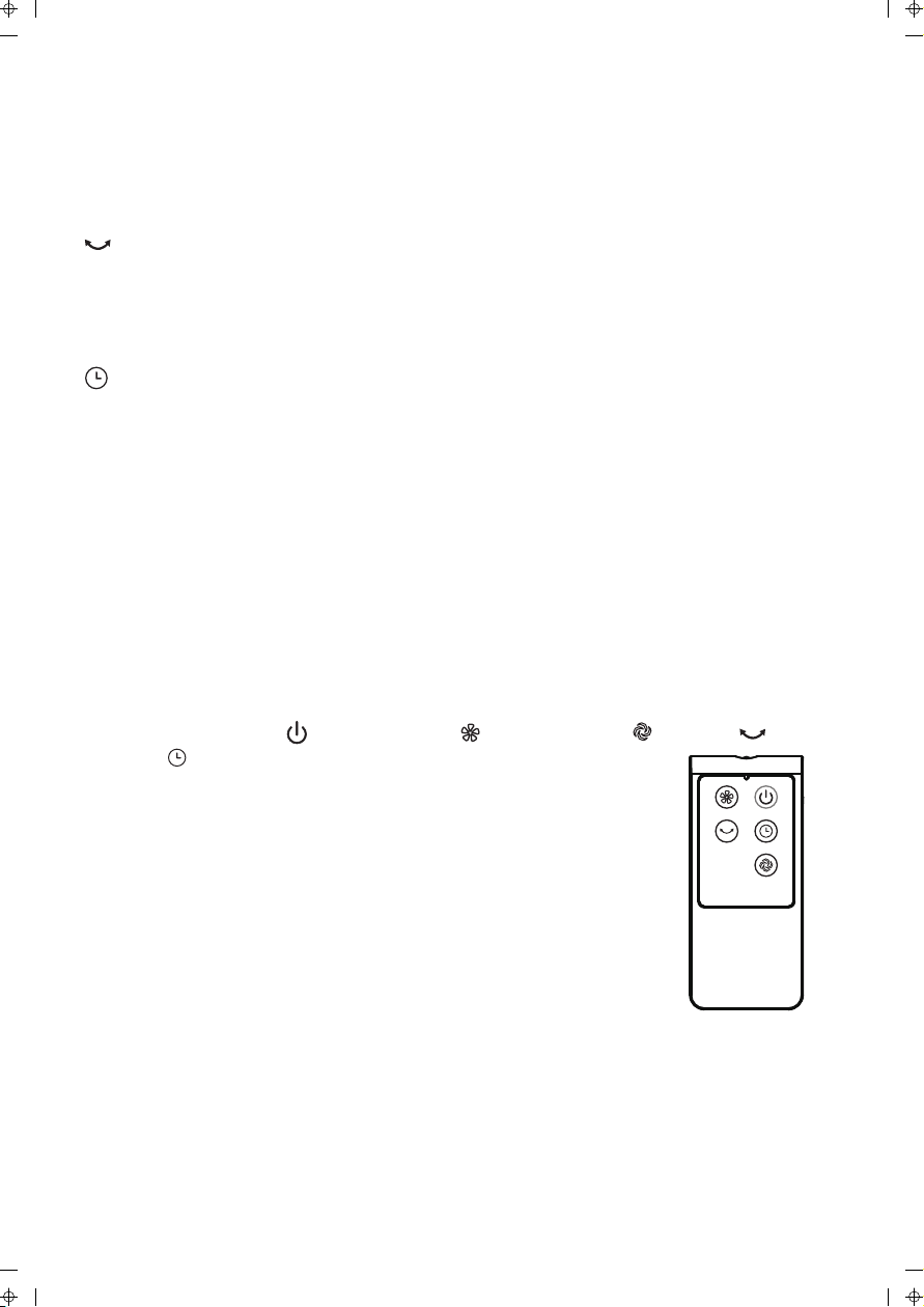
II. Remote Control (Fig. 9)
Keys such as Power ( ), Wind Speed ( ), Wind MODE ( ), OSC ( ), and
TIMER ( ) on the remote control have the same functions as
corresponding keys on the unit.
1. Remote Control Operation
(1) Point the remote control at the control panel and press the
desired key.
(2) Make sure that align the emitter at the front of the remote
control with the receiving window
(3) Avoid direct sunshine onto the control panel. This may affect
how well the remote control works.
2. Batteries
(1) Slide off the battery compartment cover located at the back of the remote.
(2) Insert the batteries, and make sure the batteries are placed as shown in Fig.10.
(3) Slide back the battery cover.
NOTE:
Use only size “1.5V AAA” manganese or alkaline batteries (NOT INCLUDED).
Do not use rechargeable batteries.
Caution: Your fan has a Safety Touch Stop Sensor function. This feature is
designed to protect children.When the fan stops, it means the guard was
touched. This is a protection feature of the unit, not a malfunction.
Fig. 9

6
PRINTED IN CHINA
The fan requires little maintenance. Do not try to fix it by yourself. Refer it to
qualified service personnel if service is needed.
1. Before cleaning and assembling, do not plug the pins into the socket.
2. To ensure adequate air circulation to the motor. Keep vents at the rear of the
motor housing from dust, fluff and etc. A vacuum cleaner can not be used to
clean these vents before unplug. Do not disassemble the fan remove fluff.
3. Please wipe the exterior parts with a soft cloth soaking a mild detergent.
Do not use any abrasive detergent or solvents to avoid scratching the sufrace.
Do not use of the following as a cleaner: gasoline, thinner, bending.
4. Do not allow water or any other liquid into the motor housing or interior parts.
MAINTENANCE INSTRUCTIONS
CLEANING
1. Be sure to unplug the power cord from the outlet before cleaning.
2. Plastic parts should be cleaned with mild soap and damp cloth or sponge.
Thoroughly remove soap film with clean water.
3. Be sure not to get water or other liquid enter the inside of the motor.
4. Dry all parts completely before reassembling and reconnecting to power
source.
(4) BATTERY WARNING AS BELOW
Do not dispose of batteries in fire, batteries may
explode or leak.
Do not mix old and new batteries.
Do not mix alkaline, standard (carbon-zinc) or
rechargeable (nickel-cadmium) batteries.
Pay attention to poles (+ and -) of the batteries.
To adjust the air flow upward or downward, push the
grilles lightly to the desired direction.
III. TILT ADJUSTMENT
Loosen the height adjustment ring and adjust the internal pole to the desired
height. Tighten the ring when desired height is achieved (See Fig. 3)
IV. HEIGHT ADJUSTMENT
To make the fan oscillate , press the “ ” OSC key on the control panel, and to
stop the fan from oscillating in the position desired , press this key again.
V. OSCILLATION CONTROL
Fig.10

7
SERVICE AND SUPPORT
(STAPLE SALES RECEIPT HERE)
NOTE: PROOF OF PURCHASE
IS REQUIRED FOR ALL WARRANTY CLAIMS
PRINTED IN CHINA
This article includes a limited warranty of one (1) year against defects in workmanship
and material (s). Excluding wear or breakage caused by abuse or improper use.
Email: [email protected]
http://www.ecohouzng.com/
For your records, staple your sales receipt to this manual and record the following:
DATE OF PURCHASE:_______________________________________________
PLACE OF PURCHASE:______________________________________________
In the event of a warranty claim or if service is required for this unit, please contact
us at the following:

8
VENTILATEUR SUR SOCLE OSCILLANT
AVEC TÉLÉCOMMANDE
Numéro de modèle: FS40-13VR
(Numéro d'article: CT4003L)
VEUILLEZ LIRE ET CONSERVER CES INSTRUCTIONS
GUIDE D’UTILISATION
E
c

9
1. Afin de réduire les risques d'incendie et de choc électrique, ne pas utiliser ce
ventilateur avec un régulateur de vitesse transistorisé.
2. NE PAS utiliser le ventilateur dans une fenêtre. La pluie peut poser un risque de
choc électrique. Ne pas laisser l’appareil fonctionner près d'un endroit où de
l'eau s'est accumulée afin d'éviter le risque de choc électrique. Ne pas immerger
l'appareil, la fiche ou le cordon dans l'eau ni aucun liquide et ne vaporiser aucun
liquide sur l’appareil.
3. Ne pas laisser l’appareil fonctionner sans surveillance.
4. S'assurer que la tension de l'alimentation électrique est la même que celle qui
est indiquée sur la plaque d'indentification du ventilateur.
5. La télécommande vendue avec ce ventilateur ne doit être utilisée qu’avec celui-ci.
MISE EN GARDE
PIÈCES
1. Le ventilateur devrait être branché à une source d’alimentation de la tension
spécifiée.
2. Brancher le ventilateur après qu’il soit complètement assemblé.
3. Ne rien insérer (doigts, crayons ou autres objets) à travers la grille pendant que
l'appareil est en marche.
4. Débrancher le ventilateur pour le déplacer d'un endroit à un autre.
5. Débrancher le ventilateur avant d'en retirer les grilles pour procéder au
nettoyage.
6. Poser le ventilateur le ventilateur sur une surface stable où il ne risque pas de
basculer lorsqu'il est en marche.
7. NE PAS utiliser dans une fenêtre, car la pluie pourrait causer un risque de choc
électrique.
CONSIGNES DE SÉCURITÉ
Veuillez lire attentivement les consignes de sécurité et les instructions.
ATTENTION
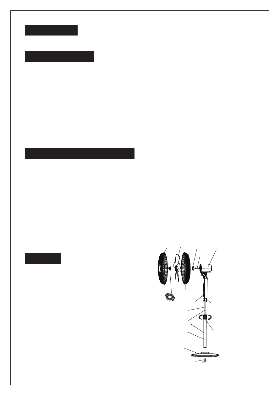
Boulon de fixation
Socle
Serrer
Serrer
Desserrer
Clavier tactile
Cône
Mât
Tige rallonge
Tige interne
Hélice Écrou de
plastique
Grille arrière
Arbre du moteur
Bouton d'oscillation
Grille avant
Vis à oreilles
Bague de
réglage de la
hauteur

10
1. Sortez la base et le mât de l’emballage, puis dévissez le boulon de fixation en
bas du mât (fig. 1).
2. Placez le mât dans la base et fixez-le à l’aide du boulon (fig. 2).
3. Dévissez la bague de raccord et réglez le tube intérieur du mât à la hauteur
désirée. Note : tirez sur ce tube s’il est complètement rétracté à l’intérieur de
l’autre tube (fig. 3).
4. Dévissez la vis à oreilles en bas du bloc de ventilation. Placez le bloc sur le mât
en l’alignant sur la rainure, puis serrez la vis à oreilles (fig. 4).
ASSEMBLAGE DU SOCLE ET DE LA COLONNE
ASSEMBLAGE DES GRILLES ET DE L’HÉLICE
1. Sortez le cône d’hélice de l’emballage, puis retirez l’écrou en plastique en le
dévissant (à l’inverse du sens horaire).
2. Placez la grille de protection arrière sur le bloc de ventilation, la poignée tournée
vers le haut.
3. Vissez l’écrou en plastique (dans le sens horaire) pour fixer la grille de protection
arrière au bloc de ventilation (étapes 1, 2 et 3 : fig. 5).
4. Retirez et jetez le petit manchon de plastique situé sur l’arbre moteur.
5. Fixez l’hélice sur l’arbre moteur en veillant à insérer la goupille de l’arbre dans la
fente de l’hélice.
6. Vissez le cône d’hélice à l’arbre moteur à l’inverse du sens horaire pour fixer
l’hélice (étapes 4, 5 et 6 : fig. 6).
7. Installez la grille de protection avant et fixez-la à l’autre grille à l’aide des clips
(fig. 7).
Rainure annulaire
Trou de fixation
Vis à oreilles
Desserrer
Fig. 1 Fig. 2
Fig. 3 Fig. 4
Ce manuel convient aux modèles suivants
1
Table des matières
Langues :
Autres manuels ECOHOUZING Ventilateur