Ecofreen MiSTER-T CYCLONE Manuel utilisateur


2 - Manual
CYCLONE
SAFETY INSTRUCTIONS
For Use By Qualified Personnel Only
When using your machine, basic precautions should always be followed, including the following.
Read all instructions. Use Mister-T Cylone only for its intended use.
Mister-T Cylcone has to be operated with DTF materials like DTF powder and DTF film.
Mister-T Cyclone comes up with 12 months warranty.
This warranty includes the whole construction of the machine, mechanical parts, electronics.
Consumable parts like filters and conveyor belt are excluded from the warranty.
The set-up and installation of the machine has to be done under supervision of an authorized person.
The installation has to be done by 2 or more persons following the instructions of this manaul.
Caution : The plug has to be pulled out of the power outlet while maintenance.
To prevent current overload, plug only one plug into one outlet.
The country that uses 110V must be electrically constructed by an electronic expert.(Refer to page 11.)
Never pull cord to disconnect the power, grasp plug and pull to disconnect from power outlet.
Protect the power cord by keeping it away from hot surfaces. Do not allow objects to sit on top of
the cord. This could cause damage to the cord and could become a fire hazard risk.
Caution : Do not operate machine with a damaged cord or if the equipment has been damaged.
Do not disassemble or attempt to repair the machine to prevent risks to injury.
Call or take it to a qualified service person for examination and repair.
Incorrect assembly or repair could increase the risk of fire, electric shock, or injury to persons
when the equipment is used.
Supervision is necessary for any machine being used by or near children. Do not leave equipment
unattended while connected.
Care should be taken to arrange the cord so that it cannot be pulled or tripped over.
To reduce the likelihood of circuit overload, do not operate other high voltage equipment on the
same circuit. (Power : 2800WATTS, 50/60 hz, 110V : about 26AMPS, 220V : about 13AMPS)
The machine should only be used by trained personal after reading and understanding of the manual.
Make sure to wear masks and safety goggles and work in a well-ventilated ara.
Important : Do not place the printer near the equipment as the printer is vulnerable to powder.
Ecofreen is not responsible for printer failures caused by placing the machine
next to the printer.

3
- Manual
CYCLONE
Table of Contents
Congratulations on your purchase of powder applicator
In order to work professionally with the machine and start production, please make sure you read
this manual carefully,
Reproduction of this manual requires written consent.
Errors and amendments of technical details excepted, all rights reserved.
We are not liable for any direct or indirect damages caused by the use of this product
Machine Parts Diagram
Specifications&Circuit Diagram
........................... 4
.................................. 5
Installation ............................................... 6
Operating Instructions
Control Panel
Filter
Nozzle&Conveyor Belt
Vacuum Cleaner
Weekly Maintenance
.....................................
.....................................
.....................................
.....................................
........................................
Operation ........................................
13
14
Trouble Shooting
.................................... 21
Maintenance
Warranty Information
(Important)
17
18
19
20
............................ 22
Table of Contents

4 - Manual
CYCLONE
Machine Parts Diagram
<FRONT>
<BACK>
Circuit Breaker
(inside)(Page.12)
Power Cord
Foot Switch
(Page.7)
Start
Button
(Page.16)
Heat Platen
(Page.15)
Ventilation
(Page.12)
Sensor
(Page.16)
Film Stand
(Page.8)
Emission filter
(Page.20)
Acrylic Lid
Control Panel
(Page.12)
* Please refer to the page.
Top Hopper
Powder Ventilator
(inside)
Cyclone(inside)
5
- Manual
CYCLONE
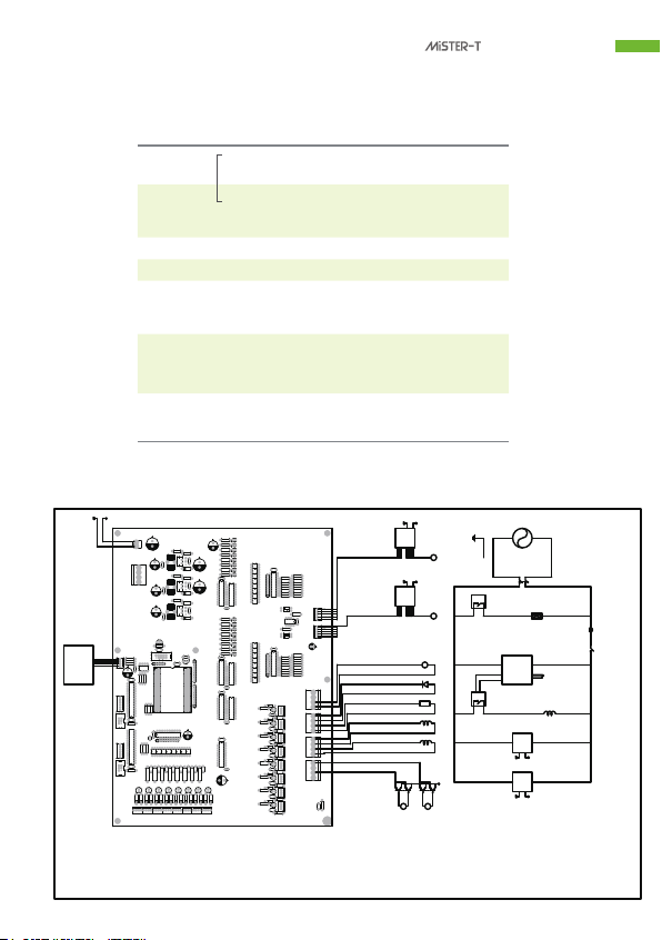
Specifications
Circuit Diagram
Dimensions Applicator
2nd Conveyor
for Dryer
( Optional )
67 cm(W) x 126 cm(L) x 196 cm(H)
26.4 inch(W) x 49.6 inch(L) x 77.2 inch(H)
66 cm(W) x 120 cm(L) x 95 cm(H)
26 inch(W) x 47.2 inch(L) x 37.4 inch(H)
35.8 inch(W) x 55.1 inch(L) x82.7 inch(H)
About 200 kgs (about 441 lb)thgieW
Conveyor Belt
45 cm x 110 cm (17.7 inch x 43.3 inch)
Lap Time
(40 cm x 50cm )
(16” x 20”)
Standard : 14 sec
High Production : 8 sec
Power Supply 2800WATTS, 50 / 60 HZ
- 110V : about 26 AMPS
- 220V : about 13 AMPS
* It may be changed according to the power of vacuum cleaners.
Packing (Wooden Pallet) 91 cm(W) x 140 cm(L) x 210 cm(H)
1 2 64
3132 34
63
33
470J
470J
470J
10KJ
TIP122
OUT_1
+24V
RS485
OUT_2 OUT_3 OUT_4
CON18. Film detection sensor
CON17. Foot switch
CON16. Start switch
CON15. N.C.
CON14. N.C.
CON13. N.C.
Start butten lamp
GND
Enable
BREAK
Speed
GND
Speed
Forward,Backward
Enable
BREAK
Forward,Backward
Case (+)
(-)
S.S.R.-2
S.M.P.S.
DC24V
(+)
(-)
S.S.R.-1
Relay-1
Relay-2
24V
S.M.P.S.
DC12V
12V
12V
(+)
(-)
Relay-1
M
(+)
(-)
Relay-2
M
Powder outlet valve motor run
Vacuum valve motor run
Powder outlet valve motor open, close
Vacuum valve motor open,close
Powder outlet vibrate motor
S.S.R.-1
M
Lamp
AC110V,
AC220V
24V
B.L.D.C.
MOTOR
DRIVE
24V
M
B.L.D.C.
MOTOR
DRIVE
24V
M
CON20. Powder outlet valve sensor
CON19. Vacuum valve sensor
Vacuum
Cleaner
Outlet
Conveyor Motor
Impeller Motor
Control
Panel
Vacuum
Valve
Motor
Powder
Outlet
Valve
Motor
Temp.
Controller Temp.
Sensor
Heat Ray
Emergency
Switch
Power
Switch

Installation
Gently open the back door of the machine and find the zipper bag inside the machine
and please check if all the components are in the zipper bag.
<Open the circled door>
<Components in zipperbag>
①
②
③
④
⑤
⑥
⑥
①Brushes(2ea) : Brushes are included due to maintenance work.
Screws(3ea) : 3 screws are included for installing film stand.
Screws(2ea) : 2 screws are included for installing the film sensor.
Bands(3ea) : 3 bands are included for tightening the vacumm cleaner to the hose.
②
③
④
Keys(4ea) : 2 keys are included
Insulating tape(1ea) : 1 insulating tape is included for tightening the vacuum cleaner and the hose.
⑤
<Inside the door>
6 - Manual
CYCLONE

Installation
1. Machine Leveling
Please ensure the machine is properly placed and leveled. Otherwise, powder in the machine
will not applied consistently.
To level the machine, turn the machine feet clockwise to decrease height and counter clockwise
to increase the height.
<Wheel>
2. Install the foot switch.
Foot switch is in the side door.
Gently unscrew the side door and place the wire in the groove as the picture below.
* Make sure not to touch the other parts inside the door.
<Unscrew the circled side door>
<Inside the side door>
<Place the wire in the Groove>
Foot
Switch
Inside
7
- Manual
CYCLONE

Installation
3. Install the film stand.
Film stand is wraped with a tinfoil and is inside the bottom door.
Unpack the film stand and install as the shown picture.
<Open the circled door>
<Components> <Place the film stand>
<Film stand is packed with tinfoil>
After placing the both of the components, assemble the film stand with the screws in the zipper bag.
3 screws are required for assembly.
*Before placing the film stand, open the
acryl lid
8 - Manual
CYCLONE
Installation
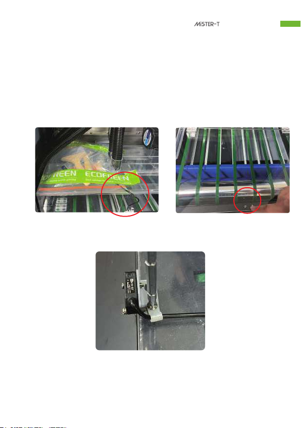
4. Install the film sensor.
Film sensor is in the zipper bag.
Unpack the film sensor in the zipper bag and install as the shown picture.
<Film sensor is packed in the zipper bag> <Assemble the film sensor>
*2 screws are required for assembly.
Regarding film sensor, please refer to page.
<Assemble the film sensor>
9
- Manual
CYCLONE

Installation
5. Connect the vacuum cleaner
Connect the vacuum cleaner to the labeld hoses as shown in the picture.
After connecting the vacuum cleander, make sure to tighten the vacuum cleaner with
insulating tape and the bands.
<Bands and insulation tapes><Labeled hose>
<Tighten the vacuum cleaner>
*bands and insulation tapes are in the zipper bag
*Both vacuum cleaners are required at lease 1100 Watts to 1300 Watts.
10 - Manual
CYCLONE
Table des matières


