ECdesigns PowerDAC-B Manuel utilisateur


© 1990-2022 - All Rights Reserved - ECdesigns!
https://www.ecdesigns.nl
/!2 15
Introduction
The PowerDAC-B is a discrete multi-bit DA converter without -any- amplifiers or buffer
circuits in the signal path.!
Balanced power-supply and resistor attenuator are used to generate the output signal.!
The PowerDAC-B can be used with an amplifier or with headphones using a (resistor based/
passive) volume control connected to the two RCA connectors on the back.!
Highlights
•Custom DAPI receiver offers high source immunity!
•Toslink input!
•Connect to (pre)amplifiers using RCA!
•Connect to headphones using RCA and (resistor based/passive) volume control.!
•Firmware upgradable!

© 1990-2022 - All Rights Reserved - ECdesigns!
https://www.ecdesigns.nl
/!3 15
Theory of operation - Block diagram
© 1990-2022 - All Rights Reserved - ECdesigns!
https://www.ecdesigns.nl
/!4 15
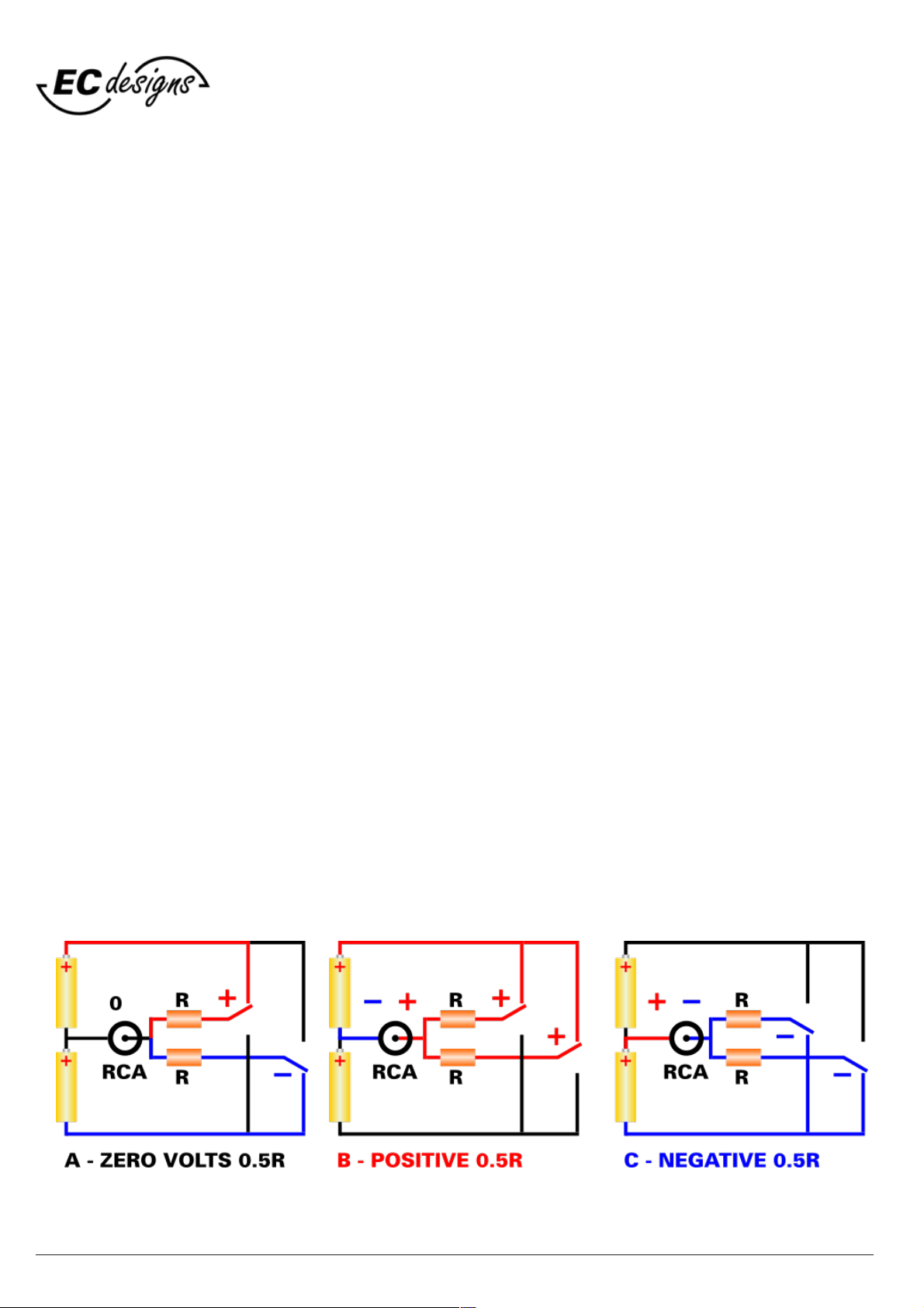
Theory of operation - RCA output
Batteries are used in the examples below to simplify the theory of operation, in reality these are a
programmable linear power supplies as shown in block diagram above.
We have: two batteries (yellow), a RCA output (black), two equal resistors R (orange), and two
electronic switches. Batteries are a short circuit for AC signals (audio signals). Resistors attenuate the
battery voltage in order to generate an analogue output signal.
A) Switches in opposite position (+ & -) currents cancel, zero volts on the RCA output.
B) Switches are both positive (+ & +) positive currents add, maximum + voltage on RCA output.
C) Switches are both negative (- & -) negative currents add, maximum - voltage on RCA output.
In all 3 cases we have two resistors with value R in parallel and batteries are short circuit for AC. So
output impedance in all 3 cases remains the same, 31.25 R.
By changing the electronic switch settings we can have no voltage, positive voltage or negative
voltage on RCA output.
But we need to program the voltage much more precisely for generating audio signals. Therefore we
use 22 electronic switches and resistors with different values (resistor array). Now we can program
262,144 different voltage levels and achieve 18 bit accuracy.
For 18 bits we would only require 18 switches, but because of the low output impedance (31.25 Ohm)
and component limitations this is not going to work in a practical circuit.
That's why we had to add more switches that represent the 3 highest and most critical bits. We
require total of 7 switches for this. The remaining less critical lower bits require 15 extra switches so
we end up with 7 + 15 = 22 switches in total.
This way we can generate highly accurate and consistent audio signals on the RCA output without
requiring any active conversion, amplifier or buffer circuit.

© 1990-2022 - All Rights Reserved - ECdesigns!
https://www.ecdesigns.nl
/!5 15
PowerDAC-B
PAGE 1
DAC type
2 x 22 bit Fractal-7 discrete, switch & resistor-based multibit power converters
Digital input
1 x Toslink 16/24 bit: 44.1 kHz / 48 kHz / 88.2 kHz / 96 kHz / 176.4 kHz / 192 kHz
Power Supply
Built-in 5V/200 mA,
Standard 220V (option: 110V)
Power Consumption
Approx. 1.25 Watt
Power Supply Cable
Included with PowerDAC-B
Output impedance
31.25 Ohms
Volume control
The PowerDAC-B has a fixed 4 Vpp (1.4v rms) output
Output voltage
The PowerDAC-B has a fixed 4 Vpp (1.4v rms) output
Output
2 x RCA output.
PowerDAC-B and
headphones
The PowerDAC-B makes it possible to directly drive many headphones (32 Ohm and up)
without any analogue amplifier or buffer in the signal path, use a passive attenuator for
volume control, e.g. resistor based.$
Bandwidth
Theoretically 100 MHz (based on switching speed)
Distortion
< 0.001% (0dB)
Technical specifications

© 1990-2022 - All Rights Reserved - ECdesigns!
https://www.ecdesigns.nl
/!6 15
PowerDAC-B
PAGE 2
POWER
Output Voltage
shifts
attenuation
in dB
Volume
4.4Vpp fixed
-
0 dB
Technical specifications

© 1990-2022 - All Rights Reserved - ECdesigns!
https://www.ecdesigns.nl
/!7 15
PowerDAC-B
PAGE 3
DAPI firmware
update!
The DAPI firmware can be updated using the USB socket and jumper setting
positions for firmware update.
Dimensions
Width: 23cm, Height: 5cm, depth: 23cm.
Weight
1.5 kg
Technical specifications

© 1990-2022 - All Rights Reserved - ECdesigns!
https://www.ecdesigns.nl
/!8 15
Jumper settings
Below are the jumper settings for PowerDAC-B.!
You will need to remove the right plate (4 screws) and then pull-out the top plate to the right to access jumper
block.!
Carefully remove or place jumpers using tweezers.!

© 1990-2022 - All Rights Reserved - ECdesigns!
https://www.ecdesigns.nl
/!9 15
Firmware update
To update the PowerDAC-B firmware you need to download the STM32CubeProgrammer.!
You need to ACCEPT Licence Agreement (click button) and on the next screen you need to fill-in your E-mail
address to be able to download STM Cube programmer (you need to use confirm via email sent to you before
you can download the STM Cube-programmer).!
The email sent to you contains the Download now button to start the download.!
Goto link below to download the STM Cube programmer (Win/Lin/Mac):!
https://www.st.com/en/development-tools/stm32cubeprog.html#get-software!
Download and install STM32CubeProgrammer!
Disconnect blue USB power cable from the PowerDAC-B.!
Use tweezers to set the red jumpers on rear of PowerDAC-B !
to PROGRAM configuration (see Jumper settings on previous page).!
Download and unzip latest pdrs-firmware.zip!
Now connect a USB cable from the PowerDAC-B to your computer and start the STM32CubeProgrammer.!

© 1990-2022 - All Rights Reserved - ECdesigns!
https://www.ecdesigns.nl
/!10 15
Screenshots here from
STM32CubeProgrammer
On the right hand side of the screen you should see:!
Port: USB1, if not then try the refresh button on the right
side of the Port dropdown button.!
If not working check jumper settings and USB cable
connection.!
Now press the Connect button.!
Then use the Open file button to load the firmware file.!
Click the Download button to load firmware file in the
PowerDAC-B.!
After message: File download complete!
Press the OK button on message window.!
Finally click on the Disconnect button to finish session.!
You can then close the STM32CubeProgrammer.!
Remove the USB cable between PowerDAC-B and PC.!
Set jumpers to the normal positions.!
After power-up PowerDAC-B the new firmware is used.
Table des matières
Autres manuels ECdesigns Amplificateur


