
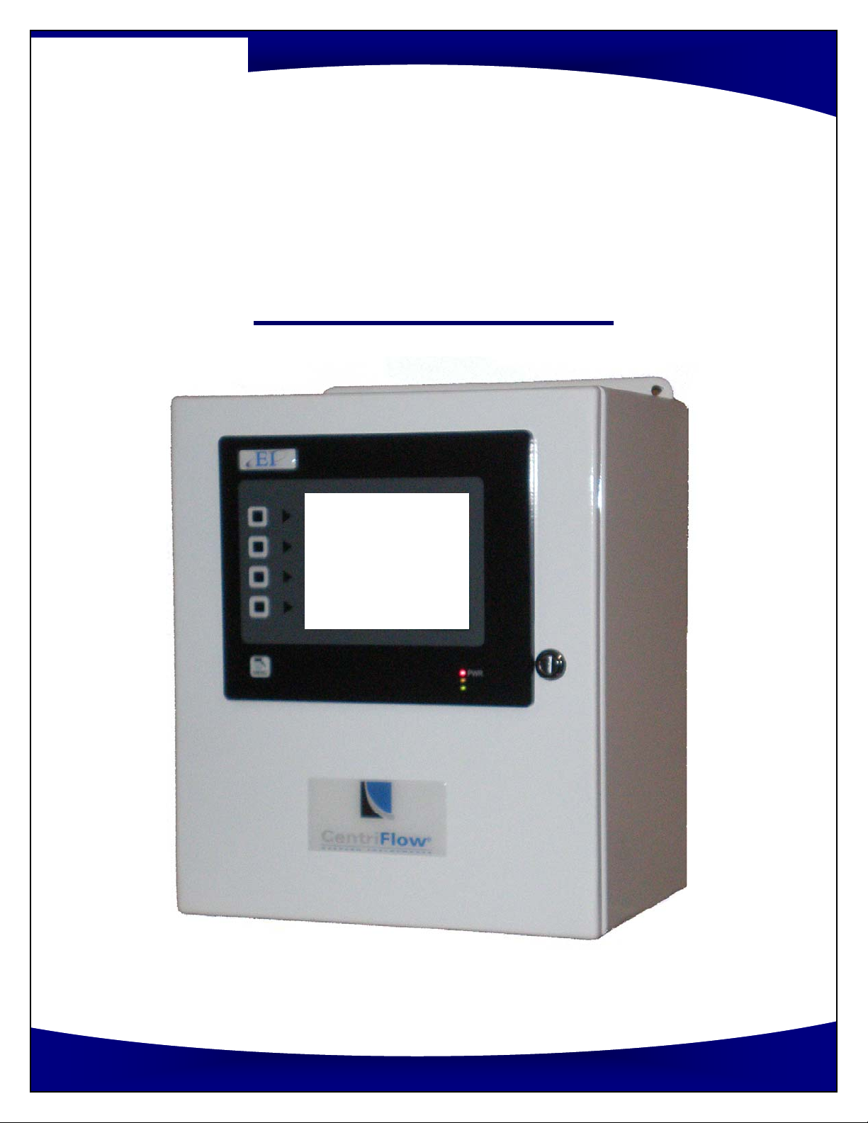
EASTERN INSTRUMENTS CentriFlow Manuel utilisateur
Phone:(910) 392‐2490
Fax: (910) 392‐2123
416 Landmark Drive
Wilmington, NC 28412 www.easterninstruments.com
CENTRIFEEDER ELECTRONICS
FOR USE WITH CENTRIFEEDER with Integrated Control Valve (ICV)
or AUXILIARY FEEDER
REV 4/17
VERSION 6.5.0 SOFTWARE
Copyright© 2017 Eastern Instrument Laboratories, Inc.
All Rights Reserved.

2
Phone:(910) 392‐2490
Fax: (910) 392‐2123
416 Landmark Drive
Wilmington, NC 28412 www.easterninstruments.com
TABLE OF CONTENTS
SAFETY
Safe Operaon................................................................................................................. 4
Warnings and Cauons ................................................................................................... 4
SafetyPlacards................................................................................................................ 5
INSTALLATION
1. Installaon Guidelines .................................................................................................... 6
Requirements................................................................................................................ 6
Trouble Areas................................................................................................................ 6
Electronics Enclosure Drawing...................................................................................... 7
Idenfying Your Components: Electronics ................................................................... 8
Idenfying Your Components: CentriFeeder with ICV ................................................. 9
Idenfying Your Components: Auxiliary Control ........................................................ 10
2. Wiring ............................................................................................................................ 11
Grounding the CentriFeeder....................................................................................... 12
Wiring the Remote Electronics Cable at Meter Module: CentriFeeder with ICV....... 13
Wiring the Remote Electronics Cable at Meter Module: Auxiliary Control ............... 14
Wiring Customer Connecons at the Electronics Enclosure ...................................... 15
Start/Stop Control: Auxiliary Feeder Only ...................................................... 16
Posion Sensor ‐CentriFeeder with ICV ......................................................... 17
Wiring the Remote Electronics Cable ............................................................ 18
CustomerConnecons Outputs...................................................................... 19
Pulsed Air (Oponal) ....................................................................................... 21
Power: Electronics Enclosure...................................................................................... 22
Power ICV Control Valve: CentriFeeder with ICV Only ............................................... 23
OPERATION
3. Pulse Blast System......................................................................................................... 24
4. A Closer Look ................................................................................................................. 26
5. Powering On .................................................................................................................. 27
6. Security Features........................................................................................................... 29
PROCEDURES
7. Stac Calibraon ........................................................................................................... 31
8. Site Calibraon .............................................................................................................. 33
9. Seng the Valve’s Upper and Lower Limits ................................................................ 36
10. Seng the Auto Delay. ................................................................................................. 38
11. Stroking the Valve ......................................................................................................... 39
12. PID Control Loop Tuning ............................................................................................... 41
13. Running the CentriFeeder™ .......................................................................................... 42
An‐Binding Funcon ................................................................................................. 45

3
Phone:(910) 392‐2490
Fax: (910) 392‐2123
416 Landmark Drive
Wilmington, NC 28412 www.easterninstruments.com
14. Filling Mode Using an Auxiliary Feeder........................................................................... 46
15. Seng the Alarm ‐Rate ................................................................................................... 48
16. Seng the Alarm ‐Totalizaon....................................................................................... 50
17. Setup of Remote Reset Capability .................................................................................. 52
18. Using the Compact Flash.................................................................................................. 53
Removing the Flash Card ............................................................................................ 53
Remote Ethernet Access............................................................................................. 55
Remote View............................................................................................................... 56
View Logs .................................................................................................................... 56
19. Changing the IP Address .................................................................................................. 59
20. Example of Establishing Communicaon to PLC: ControlLogix Unit.............................. 61
21. Tag Mapping ..................................................................................................................... 62
SCREEN GUIDE
22. Setup of Mulple Calibraon .......................................................................................... 64
23. HMI Screen Guide............................................................................................................. 67
TOP ............................................................................................................................ 67
TOP.RUN .................................................................................................................... 68
RUN.FILL..................................................................................................................... 69
TOP.CAL ..................................................................................................................... 70
TOP.COM ................................................................................................................... 71
TOP.SET...................................................................................................................... 72
TOP.IO........................................................................................................................ 73
CAL.ZERO ................................................................................................................... 74
CAL.CALs .................................................................................................................... 75
CAL.CALd.................................................................................................................... 76
CAL.RANGE ................................................................................................................ 77
CAL.INHIBIT................................................................................................................ 78
CAL.FILTER ................................................................................................................. 79
CAL.EUNITS ................................................................................................................ 80
SET.RATIO .................................................................................................................. 81
SET.FIELD ................................................................................................................... 82
SET.CALd .................................................................................................................... 83
I/O.WCOUNT(Oponal) ............................................................................................ 84
IO.ALARM .................................................................................................................. 85
IO.ALARM.SP.............................................................................................................. 86
IO.WEIGHT.OUT......................................................................................................... 87
ADV.PLC ..................................................................................................................... 88
REFERENCE
24. Definion of Terms........................................................................................................... 89
25. Cerficates........................................................................................................................ 92

4
Phone:(910) 392‐2490
Fax: (910) 392‐2123
416 Landmark Drive
Wilmington, NC 28412 www.easterninstruments.com
PLEASE READ BEFORE OPERATING THE CENTRIFLOW METER
Only authorized personnel should operate Eastern Instruments equipment. Untrained per‐
sonnel present a hazard to themselves and the equipment and improper operaon will
void the warranty.
Check for damaged parts before operang the meter. Any damaged part should be
properly repaired or replaced by trained personnel. Do not operate the meter if any com‐
ponent does not appear to be funconing correctly. Contact Eastern Instruments for assis‐
tance or for repair components.
Use the appropriate Personal Protecon Equipment as required for operang the meter
within its installaon locaon.
The various surfaces of the equipment may have sharp edges and have the potenal to
cause injury. Use the proper protecon for your hands when servicing or maintaining your
equipment.
The electrical panel (digital electronics) should be closed and the safety latch engaged at all
mes except during installaon or service. At those mes, only authorized personnel
should have access to the electronics panel. When power is acvated, AC voltage may be
present throughout the panel. Therefore extreme cauon is required.
DO NOT modify or alter this equipment in any way. If modificaons are necessary, all
such requests must be handled by Eastern Instruments. Any modificaon or alteraon
of any Eastern Instruments equipment could lead to personal injury and/or mechanical
damage and will void the warranty.
Once power has been supplied to the equipment, it is always on and
there is a potenal that product may run through it at any me.
Avoid entering or placing body parts within the equipment or its
enclosure.
Do not operate without proper training
Always wear proper PPE
NEVER service equipment while power is connected.
SAFETY
WARNINGS AND CAUTIONS
SAFE OPERATION

5
Phone:(910) 392‐2490
Fax: (910) 392‐2123
416 Landmark Drive
Wilmington, NC 28412 www.easterninstruments.com
SOME OR ALL OF THESE WARNINGS MAY BE ON YOUR METER. BE AWARE OF THE POSSIBLE
DANGERS PRESENT.
SAFETY PLACARDS
ELECTRICAL SERVICE
Electrical shock or electrocuon is possible when servicing the
electronics of any Eastern Instruments equipment. Be sure to
disconnect power before conducng any repairs on the elec‐
tronics.
PRODUCT FLOW
The Control Valve for the CentriFeeder is used only as a control
valve and does not act as an isolaon valve. A secondary isola‐
on valve is recommended to be installed before the Cen‐
triFeeder’s control valve in order to isolate the CentriFeeder
from flow during maintenance or repairs.
PINCH POINTS
The control valve of the CentriFeeder can cause serious injury
or amputaon. Keep hands clear of the control valve at all
mes.
LIVE ELECTRICITY
Live electrical wires may be present. Please note that coming
into contact with the live wires (AC Power) could cause electri‐
cal shock or electrocuon.
MOVING BLADE
WILL CAUSE
SERIOUS INJURY OR
AMPUTATION
This is a control valve, not
an isolang valve. An
isolang valve should be
installed BEFORE this
control valve.

6
Phone:(910) 392‐2490
Fax: (910) 392‐2123
416 Landmark Drive
Wilmington, NC 28412 www.easterninstruments.com
INSTALLATION REQUIREMENTS
The meter is to be used in a locaon where the product can be dropped from a fixed
height such as a conveyer, or any type of feed system, which will give a reasonably
constant inial vercal velocity. The design of the meter requires the product to contact
the Tangenal Plate and have some vercal drop.
The meter should be installed so that it is level in two planes. Use the Bubble Level on top
of the Seal Top to help.
The meter should be mounted using the mount holes only. The mounng method should
minimize vibraon and any movement. Mounng should not be done using the flange(s).
The discharge chute that the product stream empes into aer traveling through the
meter must be free flowing, meaning that it does not allow product to build up and
consequently contact the Pan of the meter.
The Electronics Enclosure and valve should be wired using only the factory cable. There is
a standard 10’ cable package that includes the Remote Electronics Cable, the valve Power
Cable, and the Valve Posion Sensor Cable supplied with the CentriFeeder™ Meter. The
cables should be cut to the exact length required. Do not coil the cables.
It is required that the Remote Electronics Cable be run through its own grounded metallic
conduit connected on the side of the module and the boom of the Electronics Enclosure.
This Cable MUST be in a separate conduit than that of the AC Power or 24 Vdc Power sup‐
plied to the Electronics Enclosure. The valve power and posion sensor signal cable can be
together in their own grounded metallic conduit.
INSTALLATION TROUBLE AREAS
The CentriFeeder™ Meter’s 4‐20mA signal is self‐powered and does not require any
addional voltage.
DO NOT RUN 480V, 240V, OR 120V AND SIGNAL LINES IN THE SAME CONDUIT. The power
and signal lines should be separate from each other and from all other devices. Running
any other power or signal lines in the same conduit could affect the performance of your
meter. Isolate both power and signal lines from each other at all mes.
The CentriFeeder™ Meter is balanced at a specific angle and should not be subject to
vibraon or movement. The mass of the mount should be at least 2 mes the mass of the
meter .
The Seal Top should be on the meter at all mes that you are not working inside the meter.
This is to keep all foreign materials out of the meter that could obstruct its movement or
impair its funconality.
INSTALLATION

7
Phone:(910) 392‐2490
Fax: (910) 392‐2123
416 Landmark Drive
Wilmington, NC 28412 www.easterninstruments.com
Electronics Enclosure
Dimensional Drawing

8
Phone:(910) 392‐2490
Fax: (910) 392‐2123
416 Landmark Drive
Wilmington, NC 28412 www.easterninstruments.com
Idenfying Your Components: Electronics
The Digital Electronics Enclosure contains the HMI, the Digital CentriFlow® Electronics (DCE),
Power Supply, Alarm Relay, Power Connecons with Knife Disconnects, and the Customer
Connecons.

9
Phone:(910) 392‐2490
Fax: (910) 392‐2123
416 Landmark Drive
Wilmington, NC 28412 www.easterninstruments.com
Idenfying Your Components: CentriFeeder with ICV
Please be sure to ground the Wago Connector for the
Transducer. To do so, run your ground wire, along with the
Transducer Cable, through the Customer Provided Conduit
and Connect to both the Meter and The Digital Electronics as
shown. The Ground Wire should aach to both the Ground
Screw on the Wago Connector Mount (Above) as well as to
the Ground Lug within your Digital Electronics (Right).
SENSOR CABLE
(WHITE)
VALVE CABLE
(BLACK)
AMPHENOL
CONNECTOR
FOR TRANSDUCER
GROUND LUG
AMPHENOL
CONNECTORS
METER MODULE
INTEGRATED CONTROL
VALVE
MEEASUREMENT
PAN ENCLOSURE

10
Phone:(910) 392‐2490
Fax: (910) 392‐2123
416 Landmark Drive
Wilmington, NC 28412 www.easterninstruments.com
Idenfying Your Components: Auxiliary Control
Please be sure to ground the Wago Connector for
the Transducer. To do so, run your ground wire,
along with the Remote Electronics Cable, through
the Customer Provided Conduit and Connect to
both the Meter and The Digital Electronics as
shown. The Ground Wire should aach to both
the Ground Screw on the Wago Connector Mount
(Above) as well as to the Ground Lug within your
Digital Electronics (Right). In the case of Digital
Electronics Upgrades, if there is no green Ground
Screw on the meter’s Wago Connector Mount,
aach the Ground Wire to one of the mounng
screws for the Wago Connector itself.
110V AC POWER
FOR THE VIBRAWEIGH
TRANSDUCER
COLUMN WIRE
WAGO CONNECTOR
FOR THE TRANSDUCER
VIBRAWEIGH ELECTRONICS
AND WAGO (OPTIONAL)
AMPHENOL
CONNECTOR
Autres manuels pour CentriFlow
2
Table des matières


