Eagle 2000F Series Manuel utilisateur
- 1 -
Operations Manual
Eagle 2000F Series Stretch Wrapper
READ ALL INSTRUCTIONS CONTAINED IN THIS
MANUAL PRIOR TO MACHINE INSTALLATION!

- 2 -
Contents
page
1. Machine Safety Information
1.1 Safety & Warnings 3
1.2 Specifications 5
1.3 Outline & Applications 8
1.4 Position of Operation 8
1.5 Safety Precautions Prior to Operation 8
2. Machine Installation
2.1 Machine Structure & Main Components 9
2.2 Transportation 10
2.3 Installation 11
2.4 Operational Environment 14
3. Operation
3.1 Operational Steps & Film Loading 15
3.2 Basic Machine Operation 16
3.3 LCD Screen Operation 17
3.4 LCD Screen Navigation & Language 18
3.5 Password Settings 22
4. Weight Scales (Optional)
4.1 Introduction 24
4.2 Error Codes 26
5. Maintenance & Troubleshooting
5.1 Troubleshooting Guide 27
5.2 Carriage Load Safety Switch 29
5.3 Turntable Home Switch 30
5.4 Turntable & Carriage Adjustment 32
6. Illustrations & Parts List
6.1 Base (Turntable) 33
6.2 Idler Roller 35
6.3 Mast 36
6.4 Carriage 38
6.5 Film Roller 40
6.6 Extended Rollers 41
7. Electrical Schematics 42

- 3 -
1.1 Safety & Warnings
Before servicing, always power down and unplug the machine from the power source.
Ensure that the correct voltage is being supplied from the power source.
Do not touch the turn table while machine is in operation.
Place all items to be wrapped in the center of the turntable.
Keep the machine and surrounding area clean, clear and free of debris to ensure safe operation.
Warning Labels
DO NOT MODIFY OR REMOVE WARNING LABELS
Turntable Edge (x2)
Platform
Platform
Use Caution When Stepping or
Walking
(Turntable may move)
Table Rotation Direction
Do Not Step

- 4 -
1.1 Safety & Warnings
DO NOT MODIFY OR REMOVE WARNING LABELS
Film Carriage
Do Not Open While Running
Control Panel (Bottom)
Electrical Hazard
Do not service machine while powered up and
connected to power source!

- 5 -
1.2 Specifications - Eagle 2000F
Power Supply
110VAC, 60Hz
Air Supply
80 PSI
Turntable Speed
(Standard 0-12 rpm) (Optional 0-20rpm) *
Turntable Motor
1 HP 750W 1420 RPM 220V 1:30 Gearbox
Turntable Diameter
64.9”
Turntable Diagonal
58”
Turntable Height
3.4”
Turntable Gear
1:5
Turntable Chain
12A-1 ISO
Carriage Up/Down
1/3 HP 1390 RPM 220V 1:60 Gearbox
Carriage Up/Down Chain
08B-1 ISO
Pre-Stretch Motor
1/3 HP 1390 RPM 220V 1:20 Gearbox
Pre-Stretch Gear Ratio
1:12
Pre-Stretch Chain
06B-1 ISO
Film Stretch
250% pre-stretch with adjustable load force
Film Lift
Photo-eye controlled to match pkg height **
Film Width
20” (standard) or 30” (option)
Adjustable Internal Limit Switches
8” Top & Bottom Rails
Max Film Height
87”
Mast Height
94”
Max Turntable Weight Capacity
5000 lbs
Max Package Height (2” Overlap)
87”
Machine Dimensions
96.5” X 59” X 99”
Shipping Weight
1295 lbs
Attachment
Ramp or Custom Heavy Duty ***
Noise
≤75 DB
Environment
Humidity ≤98% Temperature 32-104°F
1Note: Black product requires custom photo-eye installation.
2Factory ramp is for use with hand pallet jacks only. Maximum combined weight of jack and product must not
exceed 1,300lbs. Custom heavy-duty ramps are available for use with loads exceeding 1,300lbs.
3Turntable maximum RPM can be increased to 20 RPM upon request.

- 6 -
1.3 Outline and Application Field
This machine features a PLC controller. The electric subassembly uses world famous products such as
OMRON, LG and TE components. This provides a reasonable, high reliability and convenient use for
the machine. It can advance production efficiency and prevent goods from being damaged during
transportation. This machine has a wide range of applications and is used in the following industries:
chemical, fiber, tobacco, pharmaceutical, publishing, refrigeration, etc.
1.4 Position of Operation
When not operating the machine via remote control, the operator may stand in front of the operating
screen, away from the turntable and carriage. The operator must ensure that no other individual or
devices such as the forklift are at risk during operation. (See Fig. 1-1)
Fig. 1-1
1.5 Safety Precautions Prior to Operating Machine
This machine uses 110V, 60Hz, single phase power.
Do not plug into an extension cord.
Do not step on the machine when it is running
Do not install this machine on soft ground.
Install on a level surface.
Do not put the object to be wrapped on the edge of the turntable.
Turn off the power after done using the machine.
In an emergency, press the emergency stop button. This will cease movement of the machine.
Clean the machine once a day.
Only a Qualified Technician should change or test the wiring and/or electrical components.
DO NOT push, drag, or slide machine! Doing so will cause severe damage!

- 7 -
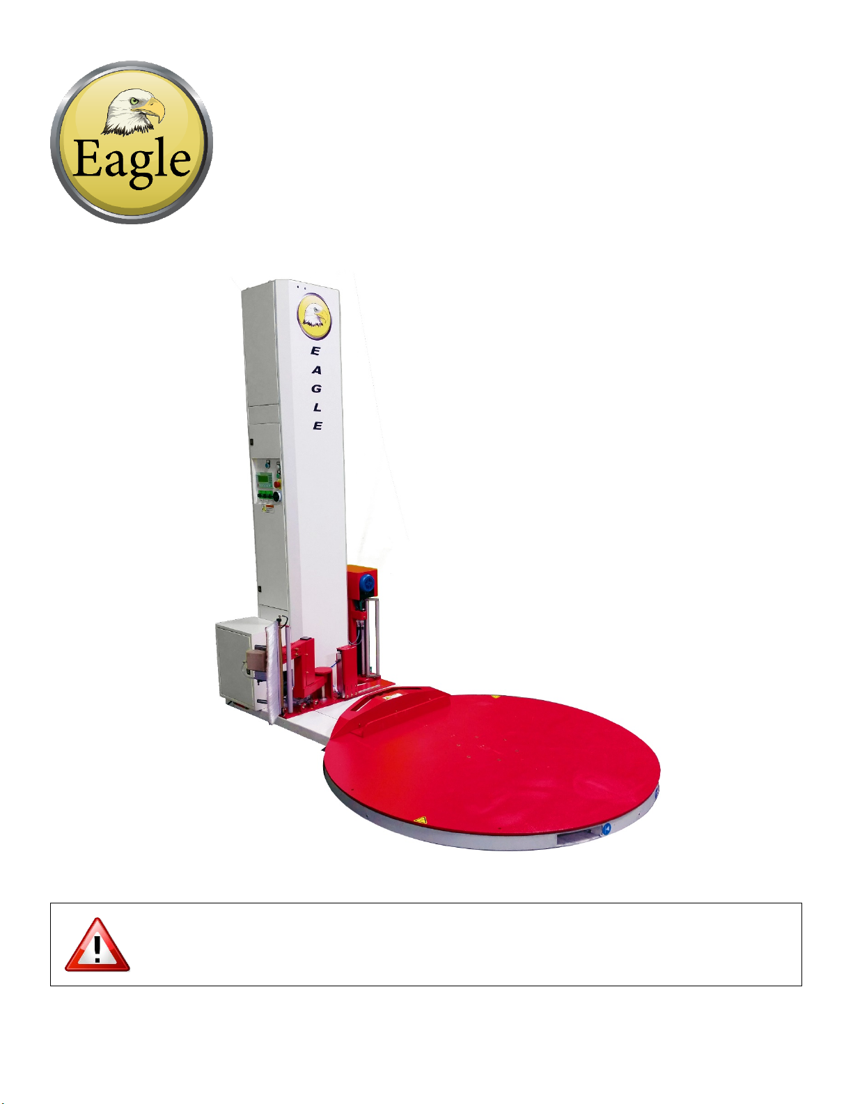
2.1 Machine Structure & Components Illustration
Fig. 2-1
Mast
Control Panel
Film Carriage
Turntable

- 8 -
2.2 Transportation
You must have at least 4ft fork tubes or tube extensions fully inserted into the machine and a forklift
rated for 3,000lbs to transport the machine safely. Do not raise the load more than 6” off of the
ground. (See Fig. 2-2)
ALWAYS USE OSHA HANDLING PROCEDURES FOR HANDLING THE
STRETCH WRAPPER AND REMEMBER TO NEVER PUSH, DRAG, OR
SLIDE THE MACHINE!
Do not transport machine from turntable when mast is
lowered!
When transporting the machine in this configuration;
1. Inspection cover must be removed before raising or
lowering the mast.
2. Carriage must be raised 8 inches
Carriage must be raised 6~8 inches before attempting
to lift machine from this end.
It is acceptable to transport machine by turntable when
mast has been raised.

- 9 -
2.3 Installation
Step 1 - Place the machine in the desired location using a tow motor or crane capable of handling a
load of 3,000lbs. (See Fig. 2-3)
Fig. 2-3
Step 2 - Remove the lower rear inspection panel on the mast prior to raising the mast. The panel is
located on the end of the machine next to the turntable motor. The panel has a warning label affixed
to it. (See Fig. 2-4a & Fig. 2-4b)
Fig. 2-4a
Fig. 2-4b
Step 3 - Lift the mast using hoisting tools. A tow motor or hoist rated for at least 3,000lbs is required.
While lifting the mast, use caution to ensure that wires and connectors are not pinched. (See Fig. 2-5a)
Once the machine is fully upright, one individual can stabilize the mast while a second individual
fastens the four M10 bolts to secure the mast to the base. The M10 bolts are to be tightened to
30ft/lbs of torque. (See Fig. 2-5b)
Fig. 2-5a
Fig. 2-5b

- 10 -
2.3 Installation
Step 4 - If installing a ramp, place the ramp by locating the ramp shoulder bolt and
placing it into the slot in the ramp. It is highly recommended to anchor the ramp to the
floor. (See Fig. 2-6)
Step 5 - Affix the carriage onto the corresponding position on the mast and fasten with four M8 bolts.
(See Fig. 2-7) Insert the connector plugs on the front of the carriage into the receptacles. (See Fig. 2-8) Do
not force the connectors together.
Fig. 2-7
Fig. 2-8*
Fig. 2-6
Table des matières
Autres manuels Eagle Équipement d'emballage


