23
2. Basic Features
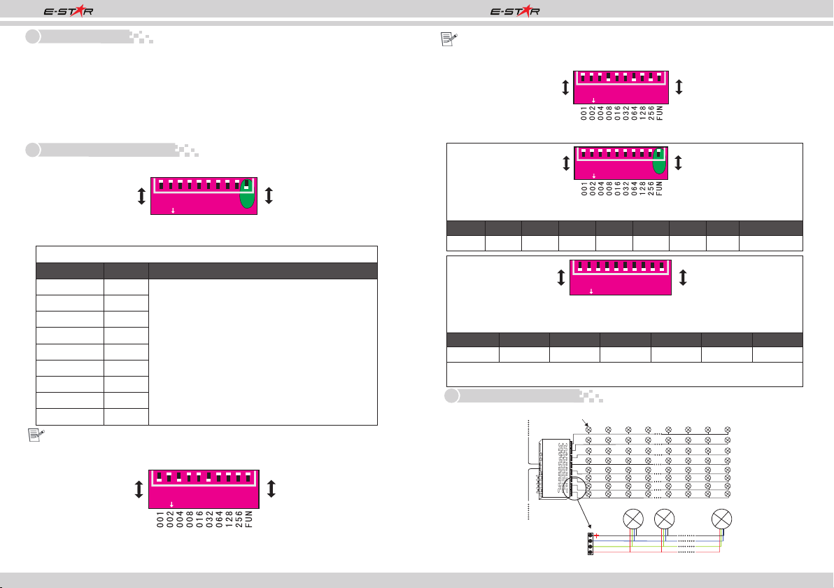
3. Decoder address setting
2. Testing function:
ES-880 DMX512 CV Decoder Manual ES-880 DMX512 CV Decoder Manual
1. Special L-PWM program technology, with more functions;
2. 24 output channels, which can connect signal color or RGB full-color lamps;
3. 0-100% smooth brightness adjusting, 256 grey steps per channel;
4. Universal standard DMX512 input protocol, addresses can be set up by DIP switch;
5. Working voltage from DC12V~DC24V;
6. With 10 auto testing modes and 8 speed adjusting modes;
FUN at “OFF” is DMX512 signal mode FUN at “ON” is auto testing mode
1 2 3 4 5 6 7 8 9 10
ON
0
1
OFF
ON
Picture 1
1. DMX initial address setting
DIP Switch
FUN at “OFF” (the10th DIP switch is upward) is DMX512 signal mode, pic 1
Value
1
2
3
4
5
6
7
8
9
001
002
004
008
016
032
064
128
256
Remark
This decoder adopts Dip switch to set the address,
the Dip switches from 1 to 9 are a kind of binary
value coding switches which used for setting DMX512
initial address code, the correlative bits is the 1-9
st th
bits of the DIP switch, the 1 bit is LSC, the 9 bit
MSC , 511 addresses totally.
DMX512 initial address is the total amount of the
Dip switches' number from 1 to 9, press Dip switch
downward (ON: at position “1”), user can get the
number of its position, if pressing upward (at
position “0”), the number of its position is 0.
Example 1: Set initial address to 37
st rd th
Set the 1 , 3 , 6 , bit of the DIP switch downward to “1”the rest to “0”
(picture 2), the summation from 1 to 9 is 1+4+ 32, so the DMX512 initial address
code is 37.
12345678910
ON
0
1
OFF
ON
Picture 2
12345678910
ON
0
1
OFF
ON
th
Such as FUN at “ON” (the 10 DIP switch is downward) is testing function.
DIP switch 1-9 at “OFF” is Black
DIP1 DIP2 DIP3 DIP4 DIP5 DIP6 DIP7 DIP8 DIP9
Red Green Blue Yellow Purple Cyan White Scan Color changing
th th
DIP8/DIP9 at “ON” (the 8 /9 DIP swithc is dowanward) is changing mode.
DIP switch 1-7 has 8 levels speed changing, DIP 7 is the fastest speed.
DIP switch 1-7 at “OFF” is speed 0
DIP1 DIP2 DIP3 DIP4 DIP5 DIP6 DIP7
Speed 1
12345678910
ON
0
1
OFF
ON
Speed 2 Speed 3 Speed 4 Speed 5 Speed 6 Speed 7
As the above pic, if several DIP switch at “ON”, it is subject to the maximum value.
if all DIP switch at “ON”, it is color fade effect of testing function, the speed is 7.
4. Conjunction Diagram
1.Connecting LED lamp:
Example 2: Set initial address to 328
th
Set the 4 , 7 , 9 , bit of the DIP switch downward to “1”the rest to “0”
th th
(as picture 3), the summation from 1 to 9 is 8+64+ 256, so the DMX512 original
address code is 328.
Picture 3
12345678910
ON
0
1
OFF
ON
R
G
B
Output Po rt
LED Light LED Lig htLED Light
LED Light
DMX IN
DMX OUT
12345678
DC+
DC-DC+DC-
DMXIN
M
DXU
OT
L -T 880
DC5V-12V


