Dynapac LT6000 Manuel d'instructions

DYNAPAC
Rammer
WORKSHOP MANUAL
WLT6000-1EN1
Box 504, SE-371 23 Karlskrona, Sweden
Phone: +46 455 30 60 00, Fax: +46 455 30 60 30
www.dynapac.com
LT6000/7000


We reserve the right to change specifications without notice.
Printed in Sweden.
Vibrating Rammer
LT 6000/7000
Workshop Manual
WLT6000-1EN1
Published workshop issues valid for these tampers:
Work shop Issue date
WLT6000 - 1EN1 2003 - 01
This workshop is valid from SN:
LT6000 PIN (S/N) *76100020*
LT7000 PIN (S/N) *77100020*

2WLT6000-1EN1
Safety instructions - Personal safety
Special caution - Machine or component damage
WARNING SYMBOLS
CONTENTS
Page
Technical specifications ................................................. 3
Oil specifications ............................................................. 3
Torque values ................................................................. 3
Tools ............................................................................... 4
Sign plate ........................................................................ 4
Disassembly the engine (LT6000/7000) ......................... 5
Reassembly the engine (LT6000/7000) .......................... 5
Disassembly and reassymbly the clutch ........................ 6
Exchange the centrifugal clutch ...................................... 6
General view for the clutch, LT6000/7000....................... 6
Carburetor LT 6000 ......................................................... 7
Carburetor LT 7000 ......................................................... 7
Recoil starter, honda ....................................................... 8
Recoil starter, honda ....................................................... 9
Valve clearance LT 6000 .............................................. 10
Valve clearance LT 6000 .............................................. 11
Valve clearance LT 7000 .............................................. 12
Disassembly the bellow ................................................ 13
Changing the bellows .................................................... 13
Reassembly the bellow ................................................. 14
Changing the bellows .................................................... 14
Disassembly the crank case ........................................ 15
Diassembly the crank case .......................................... 16
Reassembly the crank case ......................................... 17
Spring unit ..................................................................... 18
Foot ............................................................................... 19

3
WLT6000-1EN1
Torque Nm
Property class Property class
Thread x Pitch 8.8 10.9
MOiled Dry Oiled Dry
M4 x 0,7 2,5 2,8 3,4 3,8
M5 x 0,8 4,9 5,5 7,0 7,8
M6 x1 6,4 9,4 12 13,4
M8 x 1,25 21 23 28 32
M10 x 1,5 40 45 56 62
M12 x 1,75 70 78 98 110
Model Engine Idling revs/ Fueltank Engine oil Rammer leg
Operating lit. (qts) lit. (qts) lit. (qts)
speed
LT 6000 Honda GX 100 1550/3600 2,5 (2,65) 0,3 (0,32) 0,9 (0,95)
LT 7000 Honda GX 120 1400/3600 2,5 (2,65) 0,4 (0,42) 0,9 (0.95)
TECHNICAL SPECIFICATIONS
Engine oil Shell Universal Engine oil API - CF-4/SG,
ACEA - E2/B2, SAE 15W-40 or equivalent.
Rammer leg Shell Universal Engine oil API - CF-4/SG,
ACEA - E2/B2, SAE 15W-40 or equivalent.
Rammer foot M8 15Nm
Rammer foot M12 78Nm
Level glass 40Nm
Centrifugal clutch 60Nm
Crank case torque cross-wise 45 Nm
Shock absorber 25Nm
Metric thread
Bright zinc plated fzb
TORQUE VALUES
OIL SPECIFICATIONS

4WLT6000-1EN1
TOOLS
General information:
Alwys use plastic hammer when disassembly or reas-
sembly parts.
SIGN PLATE
The sign plate is mounted on the left side of the housing.
Always state Serial Number before ordering new parts
from the Spare Parts Catalogue.
W000049A

5
WLT6000-1EN1
DISASSEMBLY THE ENGINE (LT6000/7000)
1. Close the fuel valve on the tank.
2. Remove the throttle lever from the handle.
3. Remove the fuel hose from the tank.
4. Remove engine support (4) (only on LT 7000).
5. Remove the nuts (3) attaches engine to the gear
housing.
Separating the engine from the
gear housing
2
1
4
3
Fig.1 Enginewithgearhousing.
1. Gear housing
2. Engine
3. Nut x4
4. Engine support (LT700)
REASSEMBLY THE ENGINE (LT6000/7000)
Fig.2 Enginewithgearhousing.
1. Gear housing
2. Engine
3. Nut x4
4. Engine support (LT700)
5. Nut x4
6. Screw x4
1. Clean surfaces between engine, engine support and
gear housing.
2. Mount engine and torgue nuts (3) crosswise to 45 Nm.
3. Only for LT7000:
Mount engine support first by hand. When mounting
the engine support, it is important to check
parallelism between engine, gear housing and
support before the final torque. (see arrows)
4. Torque nuts (5) and screws (6) crosswise
dry to 23 Nm
1
2
3
5
64
W000037A
W000037A

6WLT6000-1EN1
1. Seperate engine from gear housing
(see previous side).
2. Unscrew the center nut (1) on the engine shaft.
3. Remove the washer (3) and the clutch (4). In some
case it is necessarily to use a puller to loosen the
clutch. The washer (3) is not valid for LT6000
4. Mount the new clutch and torque 60 Nm.
Fig.3 Engine
1. Nut
2. Key
3. Washer
4. Centrifugal clutch
Exchange the centrifugal clutch
13
4
2
DISASSEMBLY AND REASSYMBLY THE CLUTCH
General instructions for LT6000/7000
GENERAL VIEW FOR THE CLUTCH, LT6000/7000
1. Cover
2. Clutch lining
3. Centrifugal weight
4. Retaining ring
5. Spring
6. Hub
65
4
3
2
1
Clutch
Fig.4 Clutch
W000002A
W000039A

7
WLT6000-1EN1
The air cleaner must be clean before making
any adjustment. The engine must be warm
before adjusting the speed.
1
1
CARBURETOR LT 6000
Revs:
Idling revs 1550 ± 150 v/min
Engagement revs of
centrifugal clutch about 2500 rpm
Operating speed about 3750 rpm
Idle speed adjustment
1. Start the engine and allow it to warm up to normal
operating temperature.
2. With the engine idling, turn the throttle stop screw to
obtain yhe standard idle speed.
Fig.5 Carburetor
1. Throttle stop screw
Adjustment of carburetor LT 6000
CARBURETOR LT 7000
Adjustment of carburetor LT 7000
The air cleaner must be clean before making
any adjustment. The engine must be warm
before adjusting the speed.
Revs:
Idling revs 1400 ± 150 v/min
Engagement revs of
centrifugal clutch about 2500 rpm
Operating speed about 3600 rpm
1. Start the engine and allow it to warm up to normal
operating temperature.
2. With the engine idling, turn the throttle stop screw to
obtain the standard idle speed.
Fig.6 Carburetor
1. Throttle stop screw.
W000006A
W000008A
8WLT6000-1EN1
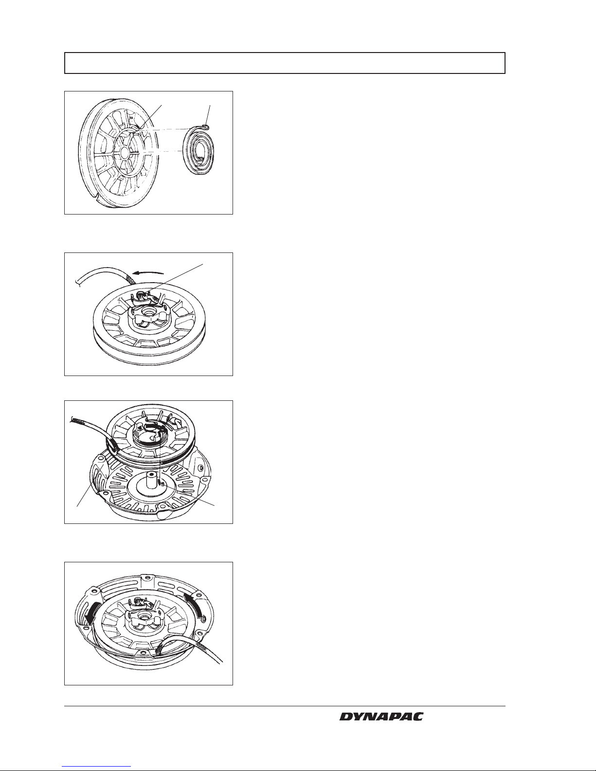
RECOIL STARTER, HONDA
1. Insert the hook (1) on the outer side of the spring
into the groove (2) inside the reel.
21
1
2
1
Fig.7 Recoil starter
1. Hook
2. Groove
Fig.8 Recoil starter
1. Tie
Fig.9 Recoil starter
1. Starter case
2. Case tab
Fig.10 Recoil starter
2. Pass the starter rope through the starter reel and tie
(1) it as shown. Wind the starter rope around the
starter reel in direction of arrow. Leave
approximately 30 cm of the starter rope outside of
the starter reel.
3. Install the starter reel on the starter case (1) so that
the spring inner hook is hooked to the case tab (2).
4. Hold the starter case and rotate the starter reel two
revolutions in the direction of the arrow for
preliminary winding.
W000009A
W000010A
W000011A
W000012A
Ce manuel convient aux modèles suivants
4
Table des matières


