
Drum SSC150 Manuel d'installation et d'exploitation

SERSER
SERSER
SERVICEVICE
VICEVICE
VICE
andand
andand
and
REPREP
REPREP
REPAIRAIR
AIRAIR
AIR
MANUMANU
MANUMANU
MANUALAL
ALAL
AL
TABLE OF CONTENTS PAGE
Safety 3
Dismantling pump head 6
Replacing front oil seals 7
Fitting rotorcase & shims 8
Rotor ass'y 9
Rotor nuts 10
Replacing rear oil seals 11
Timing gear (general & removal) 12
Removal of shaft ass'y 13
Bearings (general & removal) 13
Bearing ass'y 14
Shafts 15
Timing gear ass'y 16
Mechanical seals 18
Relief valve 20
Torque settings, wrench sizes 21
Parts list 22
SSC150
STAINLESS STEEL
CHEMICAL GRADE PUMP
SAFETYSAFETY
SAFETYSAFETY
SAFETY
PRECAPRECA
PRECAPRECA
PRECAUTIONSUTIONS
UTIONSUTIONS
UTIONS
INSIDE.INSIDE.
INSIDE.INSIDE.
INSIDE.
PLEASE SEEPLEASE SEE
PLEASE SEEPLEASE SEE
PLEASE SEE
PP
PP
PAA
AA
AGE 2GE 2
GE 2GE 2
GE 2

Page 2
This manual contains repair instructions for
complete dismantling and assembly of the Drum SSC150 pump.
For information regarding:
Pump Specifications
Installation
Operation
Routine Maintenance
Fault Finding
See:
INSTALLATION, OPERATION and MAINTENANCE MANUAL
which will have been supplied with the pump.
SAFETYSAFETY
SAFETYSAFETY
SAFETY
PRECAPRECA
PRECAPRECA
PRECAUTIONSUTIONS
UTIONSUTIONS
UTIONS
!Rotating shafts can be dangerous. You can snag clothes, skin, hair, hands, etc. This
can cause serious injury or death.
!Do not work under the vehicle when the engine is running.
!Do not work on a shaft (with or without a guard) when the engine is running.
!Do not engage or disengage driven equipment by hand from under the vehicle when the
engine is running.
!In order to avoid becoming entangled, install the power take-off and/or shaft behind the
frame rail, tanks, battery box, etc.
!If power take-off and/or shaft are still exposed after installation, install a guard.
!Install a support strap when servicing a driveshaft to prevent personal injury.
!A serious or fatal injury can occur . . .
if you lack proper training
if you fail to follow proper procedures
if you do not use proper tools and safety equipment
if you assemble driveline components improperly
if you use incompatible driveline components
if you use worn-out or damaged driveline components
if you use driveline components in a non-approved application.
!This manual contains safety instructions. Read, understand and follow this manual.
Get proper training
Learn and follow safe operating procedures
Use proper tools and safety equipment
Use proper components in good condition
Page 3

Potential Safety Hazards
Introduction
The following section gives information on handling, storage and disposal of parts and materi-
als used in the pumps which may be considered hazardous to your health.
Please pass this information on to your Safety Officer; he may need it to comply with Health
and Safety regulations.
The information contained here is brief. Full details are available and can be obtained from
your supplier.
General First Aid
If potentially hazardous substances are accidentally inhaled, or skin or eyes contaminated,
then the following basic precautions should be taken:
Inhalation - Remove to fresh air
Skin - Wash with soap and water
Eyes - Flush with water, seek medical attention
In all cases, if symptoms persist, seek medical attention.
Safety
The following safety measures MUST be carried out to prevent pump damage or injury:
1. Before installation, ensure the pump and any drive equipment conforms to all
applicable Safety Legislation.
2. Where hazardous or poisonous products have been pumped, the system should be
thoroughly neutralised and cleaned out.
3. Before proceeding to work on the pump, isolate the drive and pump from all power
and control sources.
4. Always use shut off valves to isolate the pump.
5. Make sure the pump head is depressurized before maintenance.
Page 4

Material Use Major Hazard
Silicone sealant. Gearbox seal retainers Release vapor at room
rearcover, general sealant. temperature.
Sealant. Gearbox seal retainers, rear Release vapor at room
(Red Hermetite) cover, general sealant. temperature. Highly
flammable, treat as fire
hazard.
Anti-Seize Bearings. Applied from aerosol.
Compounds. Release vapor. Dispose of
container as if pressurized.
Adhesives. Bearing nuts, relief valve Release vapor at room
(eg Permabond) adjustment rings. temperature.
Oil and Grease Oil - general lubrication Skin and eye irritant.
Grease - product seals,
timing gears, general
lubrication.
Plastic Compounds PTFE - o-rings, lip seals Releases fumes when heated.
(PTFE, gland packing.
Polypropylene, Polypropylene - gland
PVC) guards.
PVC - gland guards.
Elastomeric O-rings, lip seals. Releases fumes when heated.
Compounds
(eg Viton, Nitrile,
Neoprene, Polyurethane
Kalrez, Chemraz.
Paint External pump surfaces Releases dust and fumes if
machined. Treat waste as
fire hazard.
Page 5

Dismantling the Pump Head
Rotors
1. Ensure isolating valve to the pump are closed.
2. Unscrew the front cover dome nuts. Carefully remove the cover as some residual
pressure may still exist in the system.
Front cover
3. If the cover is stuck, simply loosen using a soft mallet aimed at the sides, where the
cover overlaps the rotor case profile. DO NOT LEVER OFF!
4. To aid further maintenance, it is advisable that the pump head is flushed out.
5. The pump is fitted with handed nuts. The top shaft has a left hand threaded nut,
and should be turned clockwise to remove it. The bottom shaft has a standard right
hand threaded nut. With the front cover removed, insert a wooden wedge to
prevent rotor rotation, while slackening off the rotor nuts for removal.
6. Before removing rotors, mark their positions relative to the shaft. Both rotors should
now be extracted by gently sliding them off their shaft splines.
7. Stubborn rotors may be released by removing the rotorcase nuts and lightly tapping
the rotorcase forward. DO NOT PRISE the rotors from behind.
NOTE: For routine maintenance it may not be necessary to remove the rotorcase. If
so, the rotors, rotorcase and o-rings mays now be inspected for wear and
damage. Refer to ROTOR ASSEMBLY for assembly of the pump.
Rotorcase
1. Disconnect pipe connections from the rotorcase.
2. Undo rotorcase nuts and remove rotorcase squarely from the locating dowels. Care
must be taken in supporting the rotorcase upon its removal, so as not to damage the
seals.
3. Special shaped shims will be found between the rotorcase and the gearcase.
These are used to determine the rotor clearances for a particular duty. Ensure shims
are marked for replacement in the same order on re-assembly.
4. It is now possible to remove the seals. One half of the seal will be in the rotorcase
and the other half on the shaft. These should be carefully removed and inspected
for wear or damage.
Page 6

Replacing Front Oil Seals
1. Follow the procedure for dismantling the pump head and removing the product seal.
2. There is now free access to the front bearing retainers which are held in place by
three socket head cap screws on each one. These should now be removed.
3. A lever may have to be used to separate the retainer from the gearcase face, as a
silicon sealant bonds the retainer to the gearcase.
4. The oil seals can be simply pressed out from the retainer and replaced using a
suitable tool. A fine grade abrasive cloth should be used to clean the internal faces
of the retainer before refitting new oil seals.
5. Thoroughly clean off the old sealant from the retainer and front face of the
gearcase. A new application of silicon sealant can now be applied.
6. Replace and tighten the six screws evenly to the recommended torque values. See
page no. 21.
7. Reassemble the pump head and product seals to the detailed procedures.
Fig. 1
Front
Seals
Front Seal
Carriers
Page 7

Fitting the Rotorcase and Shims
Correct shimming is critical to avoid damaging the pump.
Take care not to damage the product seals
when sliding rotorcase over the shafts.
First ensure that the product seals are correctly fitted. If old shims are being reused, ensure
that they are replaced in their original positions. The following procedure should be adopted if
new shims are to be fitted:
1. Fit thinnest shim over rotorcase studs both top and bottom. Fit o-rings over studs.
2. Locate the four rotorcase studs into the matching gearcase holes, ensuring that
gearcase dowels locate in holes in rotorcase. The gearcase nuts should be tight
ened to th required torque, see page 21.
3. Refit the rotors as detailed in ROTOR ASSEMBLY section.
4. By measuring the back clearances with feeler gauges, any additional shimming
required may be predetermined, to bring the clearance within tolerance.
5. Additional shims should be fitted, by repeating steps 1 and 2, and clearances
rechecked. It is essential that clearances come within tolerance, so the above
should be repeated until this is achieved. Clearances should be similar for both top
and bottom of the rotorcase.
6. Refit rotorcase and tighten gearcase nuts to the required torque, see page 21.
Radial
Clearance
0.018"
0.012"
2.851"
2.854"
Rotorcase Depth
4.263"
4.267"
Rotorcase Dia.
Back
Clearance
0.008"
0.006" mesh
0.008"
(min. at any mesh position)
Front
Clearance
0.013"
0.009"
Rotor
Length
2.833"
2.835"
Rotor Diameter
4.234"
4.236"
Page 8

Rotor Assembly
1. Before the rotors can be refitted onto their respective shafts, the sealing o-rings must be
inspected for damage and replaced as necessary.
2. To assist assembly, each rotor has a small dimple machined into it to identify the center
line of the master lobe. These must be visible from the front of the pump,
indicating that the rotors have been fitted the correct way round.
3. If rotor positions were marked prior to removal, then the rotors should be refitted one at
a time, being careful to line up the marks.
4. If no marks were made, and the pump is not fitted with hydraulic drive, then:
- Rotate the pump so that the keyway in the drive shaft is pointing vertically upwards.
- Fit rotors one at a time so that each dimple is pointing upwards on the vertical centerline.
5. If no marks were made and the pump is fitted with hydraulic drive,
then:
- Fit the first rotor on the shaft in any position.
- Rotate the pump so that the dimple on the first rotor is pointing
vertical upwards on the vertical centerline.
- Fit the second rotor on the bottom shaft, ensuring that the
dimple is also pointing upwards on the vertical centerline.
6. Rotate the shaft by hand to ensure there is no
metal to metal contact between the rotors.
7. The rotor nuts can now be tightened onto the shafts to the
recommended torque values.
8. Examine the front cover o-ring and replace as
necassary. Locate front cover and tighten the front
cover nuts to the recommended torque values.
Fig. 2 - Rotors
Page 9
Rotor Nuts
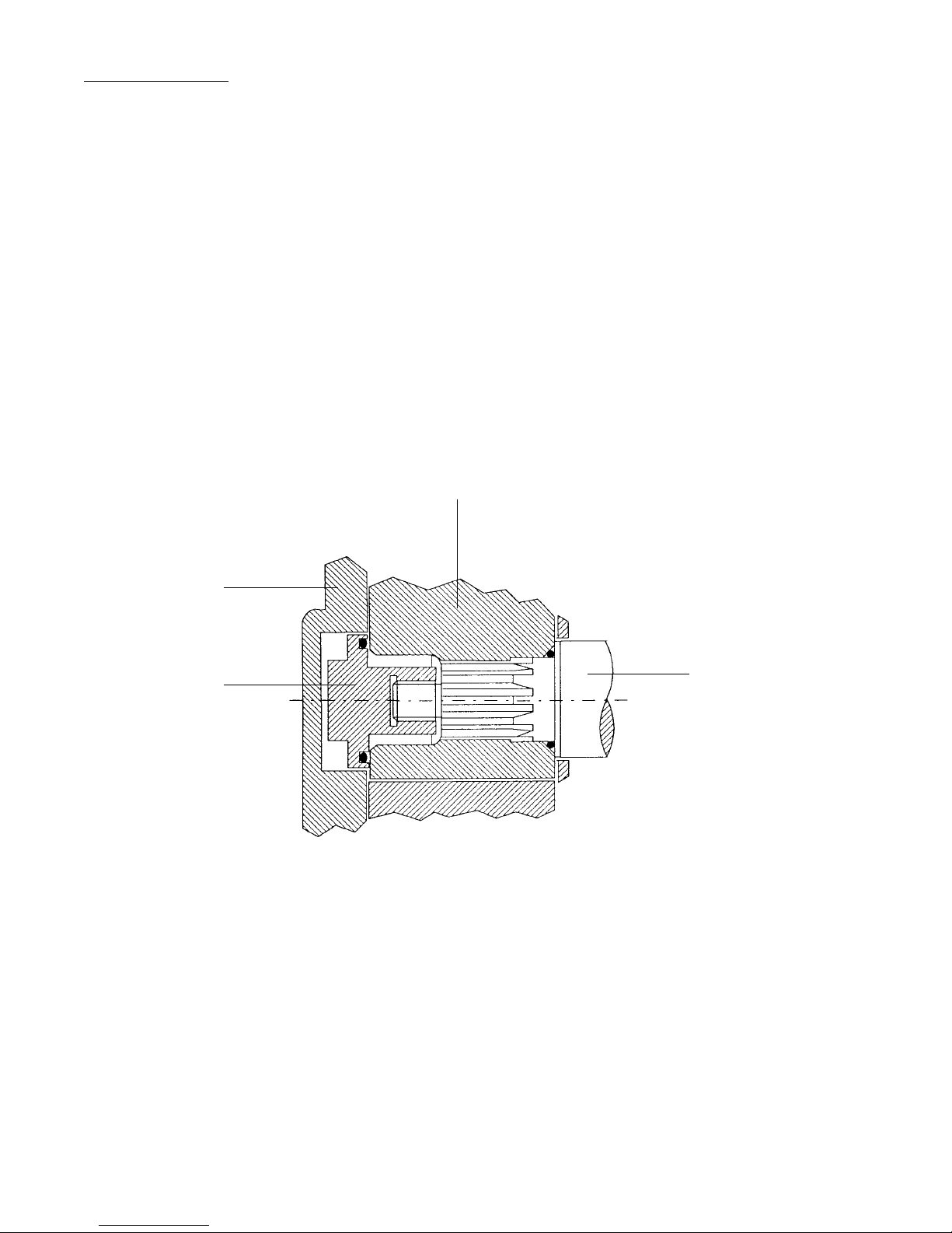
Both rotors on the pump are retained on the shaft by flanged rotor nuts. Each nut carries an
o-ring which seals the end of the rotor and shaft.
The rotor nuts are handed as follows:
Top Shaft - Left hand thread
Bottom Shaft - Right hand thread
Once the rotor nuts are removed, the o-rings must be carefully inspected for damage and
replaced if necessary.
On reassembly, the rotor nuts should be tightened to the correct torque settings.
Front Cover
Rotor Nut
Rotor
Shaft
Fig. 3
Page 10
Table des matières
Manuels Pompe à eau populaires d'autres marques


Sykes AmeriPumps
Sykes AmeriPumps GP100M Guide de dépannage

DUROMAX
DUROMAX XP WX Series Manuel utilisateur

BRINKMANN PUMPS
BRINKMANN PUMPS SBF550 Manuel utilisateur

Franklin Electric
Franklin Electric IPS Manuel utilisateur

Xylem
Xylem e-1532 Series Manuel utilisateur

Milton Roy
Milton Roy PRIMEROYAL Manuel utilisateur