Drivecon VF61 Manuel utilisateur

INTELLIGENT INVERTER
INSTRUCTION MANUAL
12-17-96 REV.
VF61
820 Lakeside Drive - Gurnee, IL. 60031
1-(800) DRIVCON (3 4-8266)
PH: (84 ) 855-9150 FAX: (84 ) 855-9650
http://www.drivecon.com Email: [email protected]
'ULYHFRQ
0 2 7 2 5 ' 5 , 9 ( 6 $ 1 ' & 2 1 7 5 2 / 6

Introduction
Thank you for your purchase of Drivecon Corporation's VF61 series inverter.
Please read through this instruction manual carefully prior to using it and get familiar ith proper
installation, iring and operations to ensure optimum and trouble-free operation.
This instruction manual describes the basic and standard operation procedures. See the catalog for
the specifications, capacity, outer dimensions, environmental conditions and so forth.
The VF61 series is to be used for a custom designed product or system, use the values ritten in the
dra ings or test report of them, not the values sho n in this manual.
Precautions for Safe Operation
1. Supply the specified voltage to the input terminals of the inverter. (If 400V po er supplied to
the 200V type inverter, the inverter ill be broken.)
2. Provide the input side of the inverter ith an MCB of the proper capacity.
3. Be sure to connect the inverter to the ground to prevent accidents.
4. Do not connect the supply line to the output of the inverter. Other ise, the inverter ill be
broken.
5. Do not connect a phase advancing capacitor to the output terminals of the inverter.
Other ise, the inverter ill be broken.
6. Before maintenance ork or inspection, turn the inverter po er off to avoid electric shock.
Wait until the "CHG" LED goes out. Note that the heatsink may be hot in some operating
conditions.
7. Do not change the parts or make reckless alterations.
8. The inverter has no noise suppression device. Please contact us if such a device is necessary.
Memory protection
We recommend that set data be protected against re riting in order to prevent misuse of the console.
(See 2.5)

Table of Contents
1. Before starting operation
1.1 Checking supplied components and parts 1
1.2 Structure of unit 1
1.3 Installation 2
1.4 Circuit construction and terminal iring 3
1.5 Peripheral devices and ire sizes 5
2. Ho to use console
2.1 Display the keys on console 6
2.2 Monitor mode 6
2.3 Function mode 7
2.4 Operation mode 9
2.5 Ho to protect data 9
3. Automatic measuring
3.1 Inputting motor data 10
3.2 Automatic measuring operations 10
4. Operation procedures
4.1 Connecting inverter to motor 11
4.2 Inputting basic data 11
4.3 Operation from console 11
5. Troubleshooting
5.1 Error messages and operations 12
5.2 Troubleshooting 13
5.3 Phase failure of input po er source 14
6. Inspection and maintenance
6.1 Periodical inspection 15
6.2 Insulation resistance test 15
6.3 Precautions for replacing printed circuit board 16
6.4 Disposal 16
7. Appendix
7.1 Enclosure dimensions 17
7.2 Typical iring diagram 18
7.3 Operator unit dimensions 19
7.4 Standard specifications 20
7.5 VF61 Programming chart 21
7.6 D61532 (D61533) Input Signal Isolator Board instructions 26
1. Before starting operation
1.1 Checking supplied components and parts.
When you receive the VF61, check it carefully.
(1) Make sure that the specifications of VF61, accessories and spare parts are properly in
accordance ith your order. Check the logo mark on the cover to see if the unit type is as
you ordered.
Example: 2R2: 2.2
3R7: 3.7 200V type: 22
5R5: 5.5 400V type: 44
7R5: 7.5 Voltage (V)
Inverter capacity (kW)
Applicable po er source INPUT: 380 to 460V, 3-phase, 50/60 Hz
OUTPUT: 2.2kW, 5.5A
(2) Make sure that the supplied VF61 hasn't been damaged during transportation.
(3) Make sure that no scre s, bolts, etc. are loose or dislocated.
If you find some problems, contact the dealer you purchased the VF61 from.
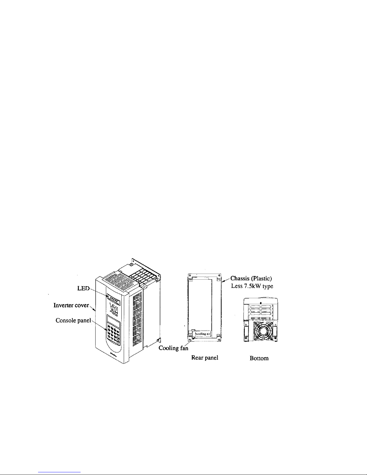
1.2 Structure of the unit
1.2.1 Appearance of unit and components
-1-
-2-
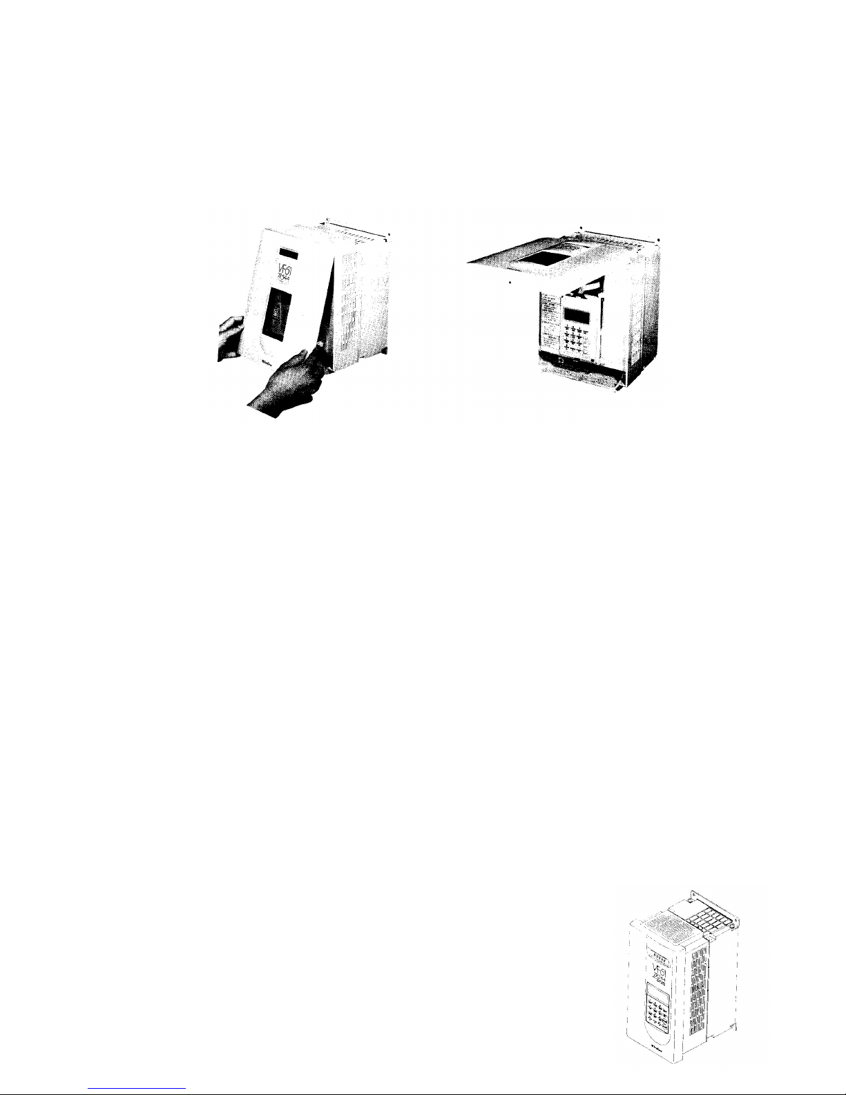
1.2.2 Opening of front cover
If you are going to inspect the VF61 or carry out automatic measuring (described in section 3
belo ), open the front cover as sho n belo .
(1) Remove the fixing scre s from the bottom of the front cover.
(2) Dra the front cover to the front.
(3) When the front cover is fully opened, push it. The cover is fixed in the Up position.
1.3 Installation
1.3.1 The installation condition has great influences upon the service life and reliability of the
inverter. Do not use the inverter in the places sho n belo . Be sure to run the inverter in the op-
erating conditions sho n in the catalog.
(1) A moist or dusty place. A place exposed to ater or oil drips.
If the inverter is used in such a place, the circuit insulation is deteriorated, resulting in shorter
service life of the parts.
(2) Extreme heat or cold out of the specified temperature range.
If the service temperature is too high, bad influences are caused upon capacitors, and parts of
cooling fan or motor, etc.
(3) A place exposed to corrosive gas
Corrosive gas deteriorates the reliability of the parts and/or connecting part.
(4) A place ith much vibrations.
Vibrations cause poor contact of the connectors, disconnection of ires, damage to parts,
etc.
1.3.2 Installation direction
If the VF61 is used separately or built into a control panel, follo the instructions belo .
(1) Installation direction
Install the VF61 vertically ith its marking "VF61" up ard as sho n belo .

-3-
(2) Securing cooling spaces
Provide the VF61 ith proper cool-
ing spaces as sho n on the right.
The cooling fan takes air from the
bottom and exhausts it to the top.
Secure enough spaces so that a ire
duct, etc. do not hinder proper
ventilation.
Install peripheral devices so that heat
generated by them does not reduce
the cooling efficiency of the VF61.
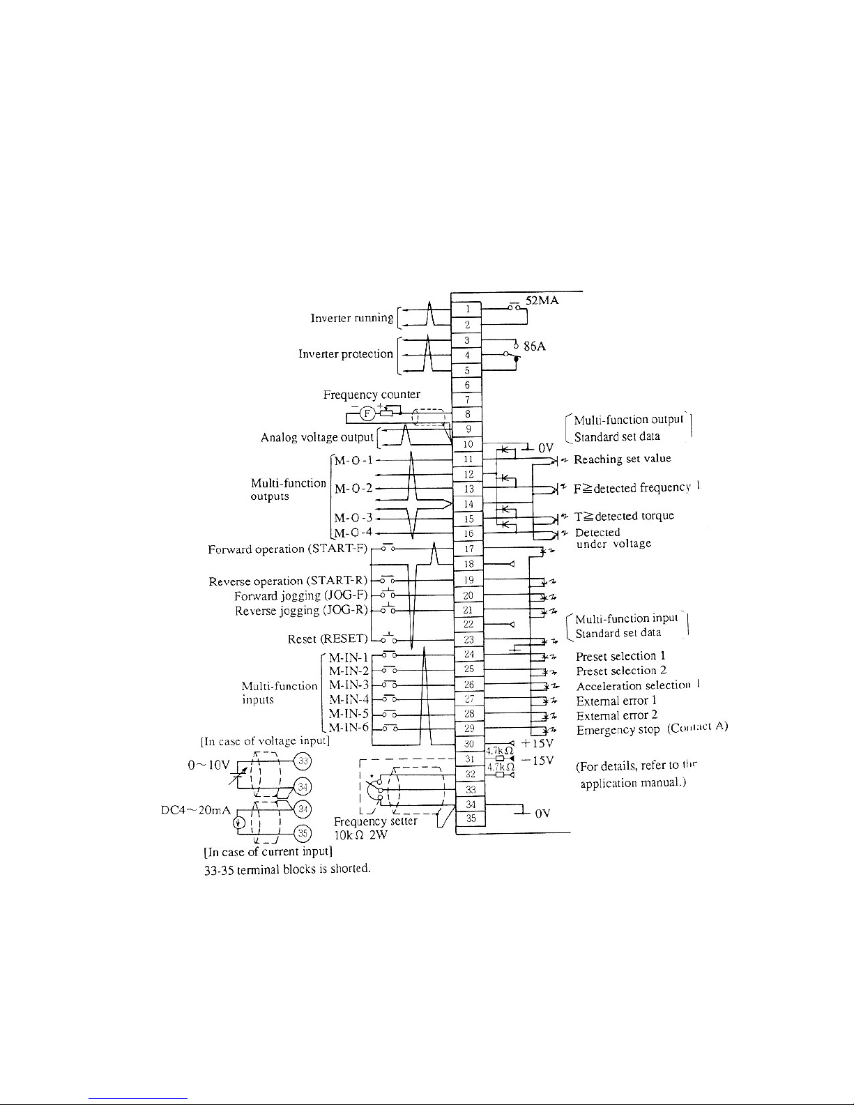
1.4 Circuit construction and riting terminal
1.4.1 Circuit construction
The follo ing sho s the standard circuit construction of the VF61.
Safety Precautions
1. Supply the specified voltage to the inverter. If 400V po er is applied to the 200V type
inverter, damage ill occur. (Note 1)
2. Be sure to provide the inverter ith an MCB of the proper capacity. See 1.5 belo .
(Note 2)
3. Be sure to connect the inverter and motor to the ground to prevent accidents.
(Note 3)
4. Connect a motor to the inverter output terminals. Do not connect the supply line to them.
Other ise, the inverter ill be damaged.
(Note 4)
Options
1. Connect a dynamic brake resistor. (Note 5)
2. Connect a DC reactor DCL. (Note 6)
-4-
Safety Precaution
Terminals 10 and 34 carry 0V of the control circuit. Never connect these terminals to GND.
1.4.2 Terminal blocks
(1) Main circuit terminal block
R, S and T Connect AC po er to these terminals. (Do not supply 400V to the
200V type inverter.)
Terminal 1 and 2 Connect the ires of the optional DC reactor DCL to these terminals.
These terminals are short circuited before shipment.
Terminal 2 and B Connect the optional dynamic braking (DB) resistor to these terminals.
Terminal 2 and 0 Connect the optional DB unit and resistor to these terminals.
(2) Control terminal block

1.5 Peripheral devices and ire sizes
1.5.1 Selection of I/O devices and precautions for main circuit iring.
The follo ing sho s the I/O devices of the VF61 unit and their ire sizes.
-5-
Type VF61-__ __ __ 22
2R222 3R722 5R522 7R522 1122 1522 2222 3022 3722 4522 5522 7522 9022
Applicable motor (HP) 3 5 7.5 10 15 20 30 40 50 60 75 100 130
Peripheral
device
Input MCCB
(Note 1) 15A 20A 30A 40A 60A 60A 100A 125A 150A 225A 300A 400A 400A
Input MC (Note 2) K20 K20 K35 K50 K65 K65 K95 K125 K150 K220 K300 K400 K400
Output MC K20 K20 K25 K35 K50 K65 K95 K125 K150 K220 K300 K300 K400
Wire size
(mm²)
Input side (Note 3) 2.0 2.0 3.5 5.5 8.0 8.0 22 38 38 60 80 150 150
Output side (Note
4) 3.5 5.5 8.0 14 14 22 22 38 38 60 80 100 150
DCL terminals
(1 & 2) 2.0 2.0 3.5 5.5 8.0 14 38 38 50 80 100 150 200
200V type
Type VF61-__ __ __ 44
2R244 3R744 5R544 7R544 1144 1544 2244 3044 3744 4544 5544 7544 11044 16044 20044 25044
Applicable motor (HP) 3 5 7.5 10 15 20 30 40 50 60 75 100 150 200 250 300
Peripheral
device
Input MCCB
(Note 1) 15A 10A 15A 30A 50A 50A 75A 75A 100A 100A 125A 200A 300A 400A 500A 600A
Input MC (Note 2) K20 K20 K20 K25 K35 K50 K50 K80 K95 K100 K125 K180 K300 K400 K600 K600
Output MC K20 K20 K20 K20 K25 K50 K50 K80 K95 K95 K125 K150 K220 K300 K400 K600
Wire size
(mm²)
Input side (Note 3) 2.0 2.0 2.0 2.0 3.5 5.5 8.0 14 14 22 38 60 80 150 200 250
Output side
(Note 4) 2.0 2.0 2.0 3.5 5.5 8.0 8.0 14 22 38 38 80 150 150 150 250
DCL terminals
(1 & 2) 2.0 2.0 2.0 3.5 5.5 8.0 14 22 38 38 60 100 200 250 250 150 (x2)
400V type
Notes:
1. The values of the input MCB sho the rated currents.
(Determine the breaking capacity from the source capacity, etc.)
2. The sho n values are those of the electromagnetic contactors MS-K series made by
Mitsubishi Electric Corp.
3. The ire sizes bet een the MCB and inverter input terminals are the sizes of the KIV or RD
ires.
4. The cable length bet een the inverter and motor should be less than 30 meters. The sho n
values are those of the CV cables.
5. If the input MC is used, the interval bet een turning on and off should be more than 10
minutes.
Safety Precautions
1. If the motor has a phase advancing capacitor, be sure to disconnect it. (If the inverter runs
ith the phase advancing capacitor connected, the inverter may be broken.)
2. Be sure to connect a circuit breaker (input MCB) on the inverter input side.
3. Be sure to connect the inverter and motor to ground.
(Use the exclusive grounding terminal.)

-6-
2. Ho to use console
2.1 Display and Keys on Console
The console has 16 columns x 4 lines LCD and operation keys as sho n belo .
Mode selector keys
Select the operation, func-
tion or monitor mode ith
the OPR, FUNC, or MONI
key. (For details of these
modes, see the follo ing
section.)
Operation selection
keys and operation keys.
Reset key
Data setting key
Numeric entry keys
(Upper)
Function entry keys
(Lo er)
^
Every press of key
alternates these
functions.
()
LCD
This mark designates
that the console is
selected to the numeric
entry key mode.
2.2 Monitor mode
Press the MONI key, and the current setting is displayed as sho n belo .
2.2.1 A monitor code (of 16 codes) and operation condition are displayed.
(See 2.2.2 for displayed items)
* MONITOR *
REM/STOP/FOR/JOG
(00)FOUT
60.0 [Hz]
Indicates selected operation keys.
Indicates a monitor code and its content.
To change a displayed monitor code, press a
numeric key (0-9), function entry key, and up
or do n arro keys.
Stored data (previous data) is displayed.
After operation starts, an operation value is
displayed.
2.2.2 Displayed code list (Items selectable in monitor mode)
Display on LCD Items Units Remarked
00 Fout Output frequency Hz
01 Fref Set frequency Hz
02 Iout Output current A
03 Vout Output voltage V
04 Torq out Torque (Torque current) % Estimated torque is displayed in
percentage
05 Vdc DC voltage V
06 Motor speed Motor (synchronous) revolution rpm
Actual revolution is displayed in ASR
operation. Revolution converted from
frequency is displayed in other
operations.
07 OL counter OL counter %
OL counter begins to count when
current exceeds rated motor current.
OL operation starts at 100%. (OL
set=100%)
08 Line speed Line speed ...
-7-
Display on LCD Items Units Remarked
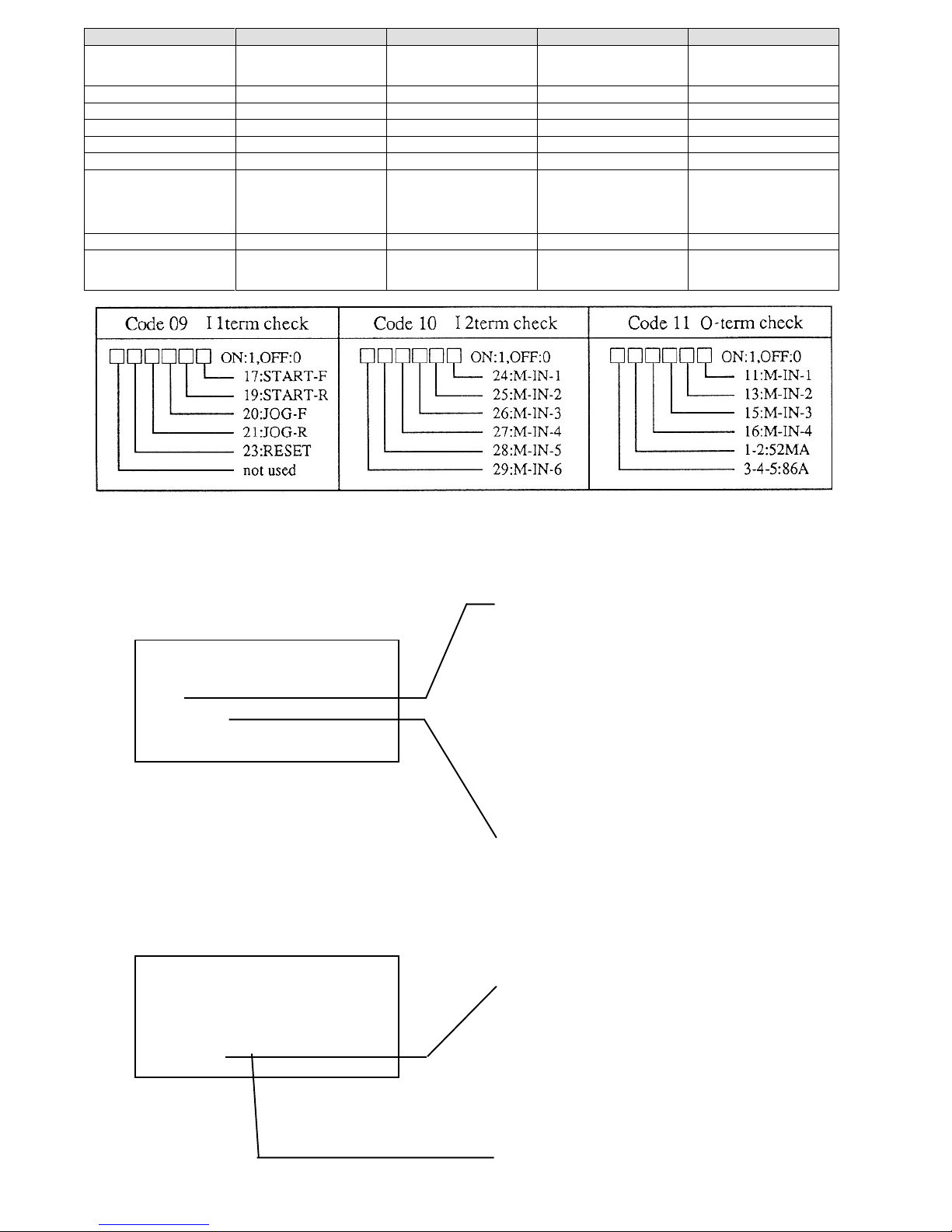
09 11term check Input terminal check 1 bit 1 is displayed when terminal block is
turned on. For meaning of each bit, se
table below.
10 12term check Input terminal check 2 bit Ditto
11 0-term check Output terminal bit Ditto
12
13
14
15 ROM Version ROM Version
"XX-XX" of ROM software version
VF61-XX-XX is displayed through
conversion of alphabetic characters
into numeric characters like A=0, B=1
and so forth.
16 Special moni For manufacturer’s adjustment
17 Trouble moni Reading error records. Contents of latest five errors and
current, voltage, etc. of these errors are
displayed.
2.3.2 Changing set data
(1) Before changing data
* FUNCTION SET *
(00)Ref(Set).F
45.0[Hz]
* .0 [Hz]
The lo est line is displayed hen the SET
key is pressed.
Display hen numeric entry is selected.
Press the SET key, the numeric entry key is
automatically established. Change data ith
the numeric entry key.
Flicker
The numeric keys may be used.
To change the set data, press the SET key.
2.3 Function mode
Press the FUNC key, and current data is displayed as sho n belo .
2.3.1 The internal data of the setting functions may be checked and changed. (See 2.3.3 belo .)
* FUNCTION SET *
(00)Ref(Set).F
45.0[Hz]
Set data is displayed.
Code number of setting function and contents
are displayed.
To change a displayed code number of the
setting function, press a numeric key (0-9),
function entry key, and up or do n arro key.
SP set-1, SP set-2 and option of sixteen basic
data codes 0 to 15 and expanded items of code
16 may be selected ith the SET, up and do n
arro keys.
Autres manuels pour VF61
1
Table des matières
Autres manuels Drivecon Onduleur


