DPS Telecom Site Dialer G3 Manuel utilisateur

USER MANUAL
Site Dialer G3
April 12, 2016 D-UM-SDXMV
Visit our website at www.dpstelecom.com for the latest PDF manual and FAQs.
(SDXMV-12004)

© 2016 DPS Telecom
This document contains proprietary information which is protected by copyright. All rights are reserved. No part of this
document may be photocopied without prior written consent of DPS Telecom.
All software and manuals are copyrighted by DPS Telecom. Said software and manuals may not be reproduced, copied,
transmitted or used to make a derivative work, by either mechanical, electronic or any other means in whole or in part,
without prior written consent from DPS Telecom, except as required by United States copyright laws.
The material in this manual is for information purposes and is subject to change without notice. DPS Telecom shall not be
liable for errors contained herein or consequential damages in connection with the furnishing, performance, or use of this
manual.
Notice
Revision History
April 12, 2016 Initial Release


ContentsVisit our website at www.dpstelecom.com for the latest PDF manual and FAQs
Site Dialer G3 Overview1 1
Shipping List2 2
Specifications3 3
Hardware Installation4 4
Tools Needed4.1 4
Mounting4.2 4
Power Connection: -48VDC4.3 5
Initial Setup5 6
LAN Connection5.1 6
Logging on to the NetGuardian5.1.1 7
Configuring the NIC Interface5.1.2 7
Site Dialer G3 Configuration for T/Mon SLIM, MINI, and LNX6 9
Step 1: Setup the Voice Pager Job6.1 9
Step 2: Setup the Site Dialer RTU Job6.2 10
Step 3: Create the Site Dialer Device6.3 10
Step 4: Setup Pager Carriers6.4 11
Step 5: How to Setup Pager Schedules6.5 11
Step 6: How to Setup Pager Profile6.6 12
Step 7: How to Assign Notification to Alarm6.7 12
Step 8: Define Voice Format6.8 13
Site Dialer G3 - Quick Turn Up7 14
How to Send Email Notifications7.1 14
How to Send SNMP Traps7.2 17
Provisioning Menu8 20
System8.1 21
User Profiles8.2 22
Ethernet8.3 24
Notifications8.4 25
Edit8.4.1 26
Email8.4.2 27
SNMP8.4.3 28
Schedule8.4.4 28
System Alarms8.5 29
Timers8.6 30
Date and Time8.7 31
System Alarms8.7.1 32

Monitoring Menu9 32
Test Call9.1 33
Stats9.2 33
Device Access Menu10 34
Reference Section11 35
Updating Site Dialer G3 Firmware11.1 35
Updating T/Mon Software11.2 36
System Alarms Map11.3 37
Technical Support12 38
T/Mon Gold and Platinum Plans13 39
End User License Agreement14 40

1
Site Dialer G3 Overview1
When combined with the T/Mon SLIM, MINI, or LNX master stations, the Site Dialer G3 delivers
another critical method of receiving alarm notifications. This application allows you to receive voice
alerts for the alarm points databased in T/Mon. You can select exactly which alarm points you want to
receive voice notifications for and the Site Dialer G3 calls your home or cell phone with verbal alarm
information. Get the important notifications you need, no matter where you are, via text-to-speech
voice alerts.
The Site Dialer G3 itself is easy to install and requires virtually no configuration. After physically setting
up the unit (mounting, power, and giving it an IP address), you're ready for the configuration on the T/
Mon SLIM, MINI, or LNX.
Immediate benefits of using the Site Dialer G3:
·Verbally annunciates incoming messages via
phone
·Dials your home or cell phone with alarm
messages already databased in T/Mon
·Ack alarms from anywhere in the field using your
home or cell phone
·Includes built-in web browser for confirming
configuration settings

2
Shipping List2
While unpacking the Site Dialer G3, please make sure that all of the following items are included. If some parts
are missing, or if you ever need to order new parts, please refer to the part numbers listed and call DPS Telecom
at (800) 622-3314.
Site Dialer G3 Site Dialer G3 Resource CD
D-PK-SDXMV-12004
X1
Site Dialer G3 UM 6 ft. USB Craft Port Cable
D-UM-SDXMV D-PR-046-10A-06
X1 X3
Ethernet Cable - 14 ft Three 3/4 Amp GMT Fuses
D-PR-923-10B-14 2-741-00750-00
X2 X2
19" Rack Ears 23" Rack Ears
D-CS-325-10A-00 D-CS-325-10A-01
X4 X8
Four Rack Screws Eight 3/8" Ear Screws
1-000-12500-06 2-000-60375-0
Power Connectors
2-820-00862-02

3
Specifications3
Hardware
Dimensions:
1.72"H x 17"W x 6.64"D
Modem:
33.6K, Cellular1
Mounting:
19” or 23” rack or wall mount
Weight:
3.8 lbs. (1.72 kg)
Discrete Alarm Inputs:
N/A
2 Discrete Alarm Length:
N/A
Power Input:
Dual -48VDC power feeds (-36VDC to -60VDC)
Analogs:
N/A
Input Range:
N/A
4 Analog Accuracy:
N/A
Control Outputs:
N/A
Max Voltage:
N/A
3 Current Draw:
350mA @ -48 VDC
Max Current:
N/A
Fuse:
Dual 3/4 Amp GMT
1 Power Outputs:
N/A
Voltage Output
Options:
N/A
Operating Temp:
32° to 140°F (0° to 60°C)
Output Current:
N/A
1 Industrial Operating Temp:
-22° to 158°F (-30° to 70°C)
Output Fuse:
N/A
Storage Temp:
N/A
Operating Humidity:
0% to 95% (non-condensing)
Audible Interfaces:
N/A
Visual Interfaces:
12 LEDs
MTBF:
60 Years
RoHS:
5/6
1 Hardware Interfaces:
1 RJ45 10/100BaseT full-duplex Ethernet port
1 USB5debug/craft port
Ordering Options:
N/A
1 RJ11 Telco jack
Software
Downloadable
Firmware:
Yes
1 D-Wire Sensor Support:
N/A
Built-in Web Interface:
Yes
Browser Support:
IE9, IE10, Firefox, Chrome...
Ping Alarms:
N/A
Protocols:
DCPx, TELNET, HTTP, Email….
SNMP Support:
V1, V2C, V3
OS Support:
XP, Vista, 7 (32 or 64 bit)
Note:
1Valid if hardware option is included.
2Minimum lengths determined with TTL voltage level alarms. Actual distance may vary.
3Current measured at rated voltage with all controls latched and all alarms triggered.
4See analog section in manual for detailed analog accuracy breakdown.
5We always recommend checking for ground potentials before using the USB port and suggest using a USB isolation device for additional protection. Without USB isolation,
ground potentials can damage your computer and/or equipment and adversely impact warranty coverage.
* This equipment has been tested and found to comply with the limits for a Class A digital device, pursuant to part 15 of the FCC Rules. These limits are designed to provide
reasonable protection against harmful interference when the equipment is operated in a commercial environment. This equipment generates, uses, and can radiate radio
frequency energy and, if not installed and used in accordance with the instruction manual, may cause harmful interference to radio communications. Operation of this
equipment in a residential area is likely to cause harmful interference in which case the user will be required to correct the interference at his own expense.
4
Hardware Installation4
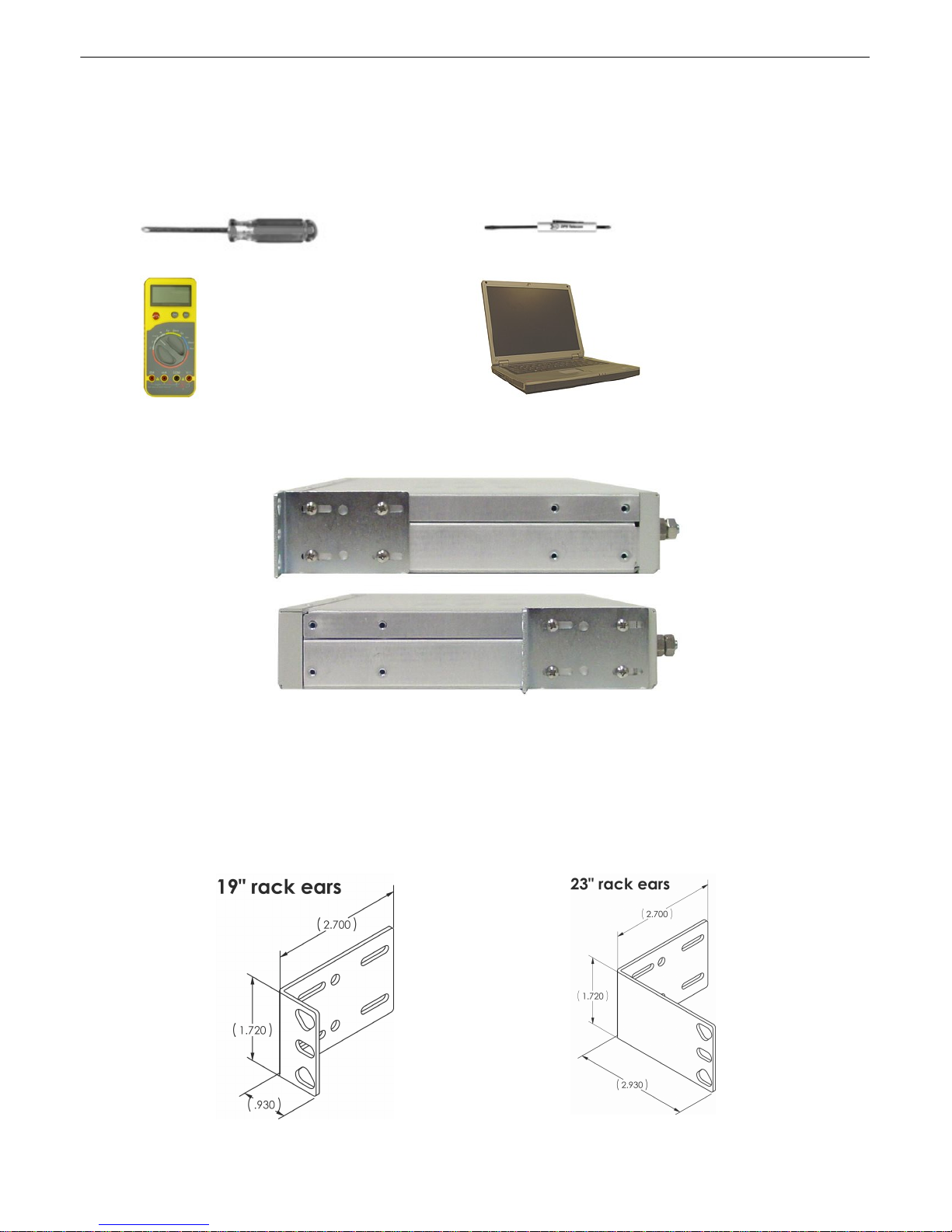
Tools Needed4.1
To install Site Dialer G3, you'll need the following tools:
Phillips No. 2 Screwdriver Small Standard No. 2 Screwdriver
Voltmeter PC with T/AccessMW software
Mounting4.2
Fig. 4.2.1. Site Dialer G3 can be flush or rear-mounted
WARNING: Leave one rack unit vacant above the Site Dialer G3 to provide adequate heat ventilation.
Site Dialer G3 mounts in a 19" rack or a 23" rack using the provided rack ears for each size. Two rack
ear locations are provided. Attach the appropriate rack ears in the flush-mount or rear-mount locations
shown in Figure 4.2.1.
Note: Rack ears can be rotated 90° for wall mounting or 180º for other mounting options.
Fig. 4.2.2
Fig. 4.2.3

5
Power Connection: -48VDC4.3
Fig. 4.3.1. Power connectors and fuses
Fig. 4.3.2 Inserting the wires into the
connector
Site Dialer G3 has two terminal barrier plug power connectors, located on the left side of the back
panel. (See Figure 4.3.1.)
Before you connect a power supply to Site Dialer G3, test the voltage of your power supply:
·Connect the black common lead of a voltmeter to the ground terminal of the battery.
·Connect the red lead of the voltmeter to the battery's –48 VDC terminal.
·The voltmeter should read between –18 and –60 VDC. If the reading is outside this range, test
the power supply.
To connect Site Dialer G3 to a power supply, follow these steps:
1. Remove the fuses from the back panel. Do not reinsert the fuse until all power connections
have been made.
2. To ground Site Dialer G3, connect a grounding wire to the grounding lug.
3. Remove the power connector plug from Power Connector A.
Note that the plug can be inserted into the power connector only one way — this ensures that
the barrier plug can only be reinserted with the correct polarity.
Note that the –48V terminal is on the left and the GND terminal is on the right.
4. Insert a battery ground into the power connector plug's right terminal and tighten the screw.
5. Insert a –48 VDC line to the plug's left terminal and tighten its screw.
6. Push the power connector plug firmly back into the power connector. If the power feed is
connected correctly, the LED by the connector will light GREEN. If the polarity of the power
feed is reversed, the LED by the power connector will be OFF.
7. Repeat Steps 2–4 for Power Connector B.
8. Reinsert the fuse to power Site Dialer G3. The front panel LEDs will blink RED and GREEN
after 20–30 seconds.
Table des matières
Autres manuels DPS Telecom Système de sécurité


Manuels Système de sécurité populaires d'autres marques


EDM
EDM Solution 6+6 Wireless-AE Manuel utilisateur

Highway Safety Group
Highway Safety Group EA401 Manuel utilisateur

Siren
Siren LED GSM Manuel utilisateur

Detection Systems
Detection Systems 7090i Instructions de montage

Se-Kure Controls
Se-Kure Controls MicroMini SK-4841 Manuel utilisateur

Siemens
Siemens FDM273 Manuel utilisateur