Menu
I. Introduction................................................................................................................................ 1
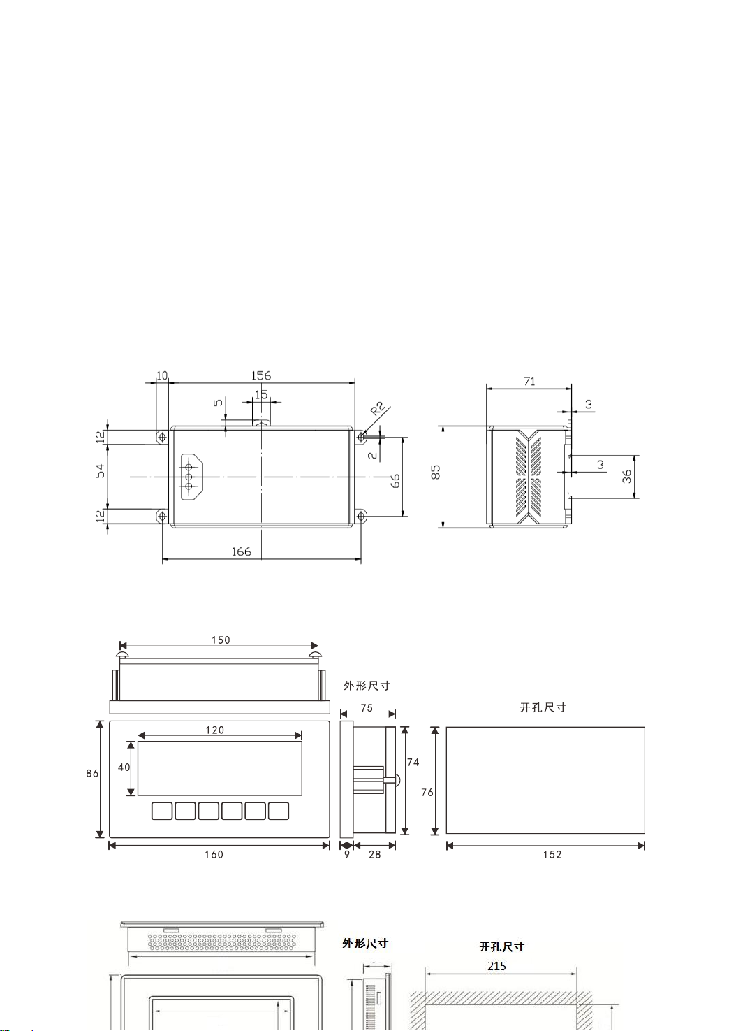
II. Structural dimensions of main engine and accessories............................................................. 2
2.1 Installation Dimension Drawing of Host......................................................................... 2
2.2 Installation dimension drawing of display panel ............................................................. 2
III. Interface Layout of Host andAccessories ............................................................................... 3
3.1 Interface layout of instrument host.................................................................................. 3
3.2 Display panel function layout.......................................................................................... 4
IV. Connection method of instrument port .................................................................................... 5
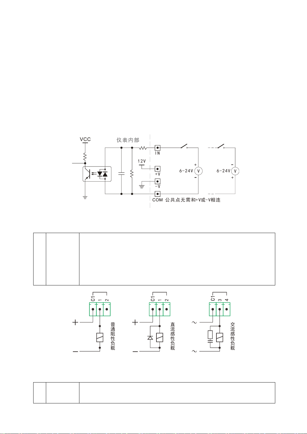
4.1 Connection method of common switch input port........................................................... 5
4.2 Connection method of switch output port........................................................................ 6
4.3 Connection method of high-speed pulse input port......................................................... 7
4.4 Connection method of large screen display..................................................................... 7
4.5 Connection method of load cell....................................................................................... 7
4.6 Connection method of communication interface............................................................. 9
V. Parameter setting..................................................................................................................... 10
5.1 Function and operation of setting buttons on the display panel..................................... 10
5.2 Introduction of instrument parameters........................................................................... 12
5.3 Password control and permitted operation items........................................................... 12
5.4 Operation steps of password login................................................................................. 13
5.5 F parameter setting and lookup table............................................................................. 13
5.5 P parameter setting......................................................................................................... 17
VI. Weighing and calibration of instruments............................................................................... 18
6.1 Physical calibration........................................................................................................ 18
6.2 Calculation method calibration...................................................................................... 19
VII. Setting of other working parameters.................................................................................... 21
7.1 Parameter setting and protocol of full-function communication port............................ 21
7.2 High-speed pulse input port as large screen output port................................................ 22
7.3 High-speed pulse input port shall be a common input port. .......................................... 22
7.4 Modify the login password............................................................................................ 22
7.5 Settings of panel display content................................................................................... 23
7.6 Timed shutdown function .............................................................................................. 24
7.7 Input and output position adjustment............................................................................. 25
VIII. Instrument testing and other operations.............................................................................. 27
8.1 Instrument test function................................................................................................. 27
8.2 Instrument power-on self-test and fault display code.................................................... 28
8.3 The instrument weight is set to zero and the total accumulated quantity is cleared. ..... 29
8.4 Start and Exit of Process................................................................................................ 30
8.5 Restore factory settings.................................................................................................. 30
IX. Appendix ............................................................................................................................... 32
Appendix 1 Top Loose Communication Protocol................................................................ 32
Appendix 2 Command of Continuous Sending Mode......................................................... 40
Appendix 3 Modbus RTU communication function code table .......................................... 42