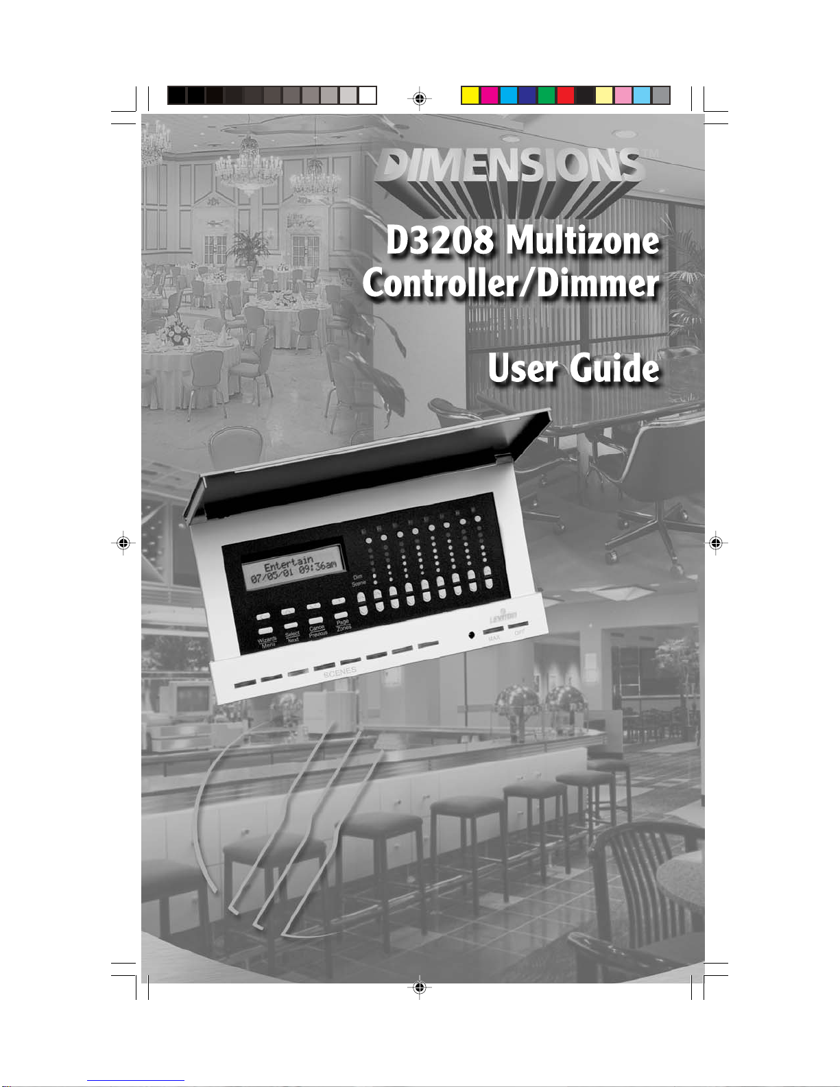
m-Dimension D3208 Manuel utilisateur

DI-000-D3208-00A-2/13/02 3/6/02, 11:04 AM1

TABLE OF CONTENTS
FEATURES.................................................................................... 1
INTRODUCTION........................................................................... 2
DESCRIPTION .............................................................................. 3
SPECIFICATIONS......................................................................... 4
QUICK REFERENCE GUIDE ........................................................ 5
INSTALLATION INSTRUCTIONS .................................................. 7
USER INTERFACE ..................................................................... 13
PROGRAMMING AND OPERATION .......................................... 14
MENU TREE ............................................................................... 33
TROUBLESHOOTING ................................................................ 34
APPENDIX
Latitude/Longitude Chart................................................ 38
DI-000-D3208-00A-2/13/02 3/6/02, 11:04 AM2

FEATURES
•Allows dimming of 6 local loads per Multizone Controller (incandescent,
tungsten, magnetic low-voltage, Advance Mark X fluorescent, neon, cold
cathode and non-dimming)
•Controls up to 248 zones
•Remote zone control capability of up to 248 zones
•Allows 32 scenes per group, per single configuration
•Provides control of 8 partitioned areas in up to 256 configurations
•Expansion of up to 30 additional D3208 Controllers
•Group and individual zone DIM/BRIGHT capable
•Configurable fade-transition rates (0-59 seconds and 1-120 minutes)
•User-friendly Wizards for easy setup/operation
•Two-line, 32 character LCD (Liquid Crystal Display)
•Automatically turn ON/OFF lights at dusk and/or dawn (astronomical clock)
•Create up to 64 timed events which can reoccur year after year
•Create up to 32 lighting scenes
•Access any of the 32 scenes from the from the Programmer front panel (8 at
any one time)
•Customizable zone names of up to 16 characters
•Compatible with other D3200 components that interface with the LCnet
system; PC based programming through D3200 Setup Software and Leviton
SmartJack, a wall-mounted Scene Controller, and a handheld remote control
(optional)
•Access any of the scenes using 8 learned Infrared codes utilizing a Leviton
IR Remote, Cat. No. NE210 or 32 codes with any standard IR Remote
•Real Time clock retains correct time, with accuracy of 15 seconds, in
absence of power typically for 2 weeks
•Guaranteed 15 minute accuracy for any North American (US, Canada,
Mexico) locality based on Sunrise/Sunset calculations.
•Security options
FEATURES
For more information, refer Leviton’s website at www.leviton.com/D3200
1
DI-000-D3208-00A-2/13/02 3/6/02, 11:04 AM3

INTRODUCTION
The Leviton Multizone Zone Controller/Dimmer, Cat. No. D3208, provides
advanced, multi-point scene control for commercial and high-end residential
lighting applications. The D3208 is a user-friendly, self-contained unit that can
be used to control—at one time from the front panel—up to six zones of lighting
and two auxiliary LCnet dimming or switching loads in a room or group of rooms
via a series of push-buttons and “Wizard” menus. Suited for areas with
removable partitions, the D3208 accommodates combine/separate functionality,
a host of customizable settings, and features an infrared receiver for use with a
handheld remote control. Although the unit will often be used as part of a
comprehensive D3200 dimming system attached via a communication bus, it
may also be used solely as a dimmer attached to six loads.
A series of intuitive wizards displayed on the unit’s LCD simplifies the user
interface. A number of push-buttons guide the user through the wizards, which
can be used to program the Multizone Controller—as can Leviton software. The
unit will normally display the selected scene’s name, date, and time in it’s Main
Screen, and by simply pressing the applicable scene buttons, end-users can
control their preprogrammed lighting. The Multizone Controller can send
commands to up to 248 individual lighting and appliance loads.
The Multizone Controller provides the capability to program up to 32 customized
Lighting Scenes. With Scene Lighting, selected lighting loads can be
programmed to turn ON at desired brightness levels or OFF when required; in
either a single room or a group of rooms. Lighting Scenes can be preset for
home theater viewing, hall presentations, dining, entertaining and a wide range
of other activities. Lighting Scenes can be easily changed at any time by
pressing the applicable scene button.
INTRODUCTION
2
DI-000-D3208-00A-2/13/02 3/6/02, 11:04 AM4

DESCRIPTION
The D3208 can function in two ways: One, as a self-contained dimmer for loads
directly attached to it and two, as a control unit for other remote devices (which it
can also power) attached to the Leviton Control Network (LCnet) communication
bus.
The Multizone Controller is designed to be customized on the job site or
residence in minutes with customized zone and scene names such as
“Chandelier,” “Presentation,” and so on. If the zone is local to the Multizone
Controller, the zone number appears above the LED column indicating each
zone’s brightness level. The “A” for auxiliary will light up to indicate that the zone
is wired to the LCnet but not directly to the Multizone Controller. During
adjustment, the LCD displays the exact zone light level so that repeatable
settings can be achieved. The D3208 provides eight different scene buttons; the
active scene button will remain lit. Once scenes are programmed, any zone may
be individually dimmed or brightened without affecting the rest of the scene. A
number of other helpful push-buttons round out the functionality: Group Dim,
Group Brighten, Maximum Brightness, and OFF.
The D3208 offers programming capabilities including each individual zone’s
minimum level and name. Scene changes can also be scheduled based on
clock time or dawn and dusk, and can even be set to change on a seemingly
irregular schedule—ideal for security reasons.
As part of a much larger family of digital controls and systems, the D3208 can
communicate with other LCnet control stations across its high-speed serial data
line. This allows it to be incorporated into a system with other Dimensions 3200
Zone and Scene Controllers, including the six-zone D3206 Multizone Controller/
Dimmer, as well as with remote dimmers and switched loads such as motors.
DESCRIPTION
3
DI-000-D3208-00A-2/13/02 3/6/02, 11:04 AM5

SPECIFICATIONS
Electrical
Input: 120VAC, 60Hz, +/-10%
Isolated Output: 24VDC @150mA
Power Output: 1920W/VA total
1000W/VA max. per zone
1200W/VA max. per side
Minimum Load: 15W
Surge protection: Surge Suppression for voltage surges up to
6000V and current surges up to 3000A
Load Types: Incandescent, Tungsten, Magnetic Low-Voltage
Transformer, Advance Mark X Electronic
Fluorescent Dimming Ballast, Neon, Cold
Cathode, and non-dimming loads
Testing/Code Compliance: UL Listed, CSA Certified
FCC Statement: This device complies with part 15 of the FCC
Rules. Operation is subject to the following two
conditions: (1) This device must not cause
harmful interference, and (2) This device must
accept any interference received, including
interference that may cause undesired operation.
Real Time Clock: Accurate within 15 seconds per week,
with or without power
Leap year compensation
Calculating of Sunrise and Sunset, given
the correct latitude and longitude, to within
15 minutes
Environmental
Operating Temperature: 0°C to +40°C
Software
Programmer has been specified with sufficient permanent memory for 20
years to hold :
-32 Scenes
-64 Time schedules
SPECIFICATIONS
4
DI-000-D3208-00A-2/13/02 3/6/02, 11:04 AM6

QUICK REFERENCE GUIDE
Use this section for a quick reference for an overview of the operational features
of the D3208 Multizone Controller after initial setup and programming has been
completed. For more detailed features, please refer to the Programming/
Operation section of the manual.
CALL SCENE: Used to choose which of the 32 programmed scenes are to be
called or activated.
•Press a SCENE button (refer to Figure 4) to call or activate a programmed
scene.
ADJUST ZONE LIGHT LEVEL: Used to increase or decrease the
percentage of light level for selected zones.
•Press the Zone Dim/Bright buttons to increase or decrease the percentage
of light level for individual zones (refer to Figure 4).
•Press the Dim Scene buttons to increase or decrease the percentage of
light level for all zones (refer to Figure 4).
CHANGE SCENE BANK: Use to choose which of the 32 programmed
scenes can be accessed and which SCENE buttons will control those scenes
(01-08, 09-16...25-32).
•Press the Function button (refer to Figure 4) to toggle though the Scene
Banks (01-08, 09-16...25-32) and then press a SCENE button to activate
that bank.
PROGRAMMING SCENE: Use to program, name and set fade-transition
rates to desired scenes.
•Press and hold down a SCENE button for approximately 8 seconds to
access program mode.
•Press the Up or Down and Left or Right buttons to
Edit Scene Name (i.e., Hallway Lights). Press the
Select/Next button to save entry and proceed.
•Press the Up or Down button to set the desired fade
time (default, 0:00 seconds to 2h00m) . Press the
Select/Next button to save entry and proceed.
•Press the Dim/Bright buttons to turn lighting loads ON, OFF, or adjust
percentage of lighting level (refer to Figure 4).
•Repeat steps for additional scenes.
Edit Scene Name:
SCENE 01
SCENE 01
Set Fade: <DEF>
5
DI-000-D3208-00A-2/13/02 3/6/02, 11:04 AM7

PAGE TO OTHER CONTROLLERS: If using multiple Multizone Controllers,
use this feature to access all Multizone Controllers addressed on the network.
You can then modify or adjust lighting levels previously programmed.
•Press the Page Zones button to access the desired Controller (refer to
Figure 4).
•If access is not allowed to other Multizone Controllers, refer to the Setup
Wizard, Step 15 to include remote panels on the network.
CHANGE CONFIGURATIONS: If using multiple Multizone Controller
configurations, use this feature when changing the partition setup in a room.
NOTE: If partitioning has not been setup yet, follow the SETUP WIZARD to
program the Panels section before proceeding.
•Press the Wizards button and then the Up or Down
button to select the Config Wizard. Press the Select/
Next button to access the CONFIG WIZARD.
•Press the Select/Next button to access the Set Config
screen.
•Press the Up or Down buttons to select the desired
Configuration (001-256).
•Press the Select/Next button to save entry and return
to the CONFIG WIZARD screen.
•Press the Wizards button to return to the Main
Screen.
QUICK REFERENCE GUIDE
Use , v or SEL
<CONFIG WIZARD>
V
Use , v or SEL
>Set Config
V
CONFIG 001
SELECT: 001
Use , v or SEL
<CONFIG WIZARD>
V
6
DI-000-D3208-00A-2/13/02 3/6/02, 11:04 AM8

INSTALLATION INSTRUCTIONS
WARNING: TO BE INSTALLED AND/OR USED INACCORDANCE WITH
APPROPRIATE ELECTRICAL CODES AND REGULATIONS.
WARNING: IF YOU ARE NOT SURE ABOUT ANY PART OF THESE
INSTRUCTIONS, CONSULTA QUALIFIED ELECTRICIAN.
WARNING: DO NOT CONNECT LINE VOLTAGE WIRES TO LOW-VOLTAGE
TERMINALS.
WARNING: TO REDUCE THE RISK OF OVERHEATING AND POSSIBLE
DAMAGE TO THIS DEVICEAND OTHER EQUIPMENT, DO NOT INSTALL TO
CONTROLA RECEPTACLE.
WARNING: USE ONLY WITH THE APPROPRIATE ADVANCE MARK X™
120V ELECTRONIC DIMMING BALLASTS FOR CONTROLLING THE
SPECIFIC FLUORESCENT LAMPS.
CAUTION: USE WITH INCANDESCENT, TUNGSTEN, 120V HALOGEN
FIXTURES, COLD CATHODE, MAGNETIC LOW- VOLTAGE TRANSFORMER
FIXTURES, OR MARK X™ 120V ELECTRONIC DIMMING BALLASTS ONLY.
DO NOT USE THIS PRODUCT TO CONTROL ELECTRONIC (SOLID STATE)
LOW- VOLTAGE TRANSFORMERS.
OTHER CAUTIONS:
1. WHEN A MAGNETIC LOW- VOLTAGE CIRCUIT IS OPERATED ATA DIM
LEVEL, WITH ALL LAMPS INOPERATIVE, EXCESS CURRENT MAY
FLOW THROUGH THE TRANSFORMER. TO AVOID POSSIBLE
TRANSFORMER FAILURE DUE TO OVERCURRENT, USE A
TRANSFORMER THAT INCORPORATES THERMAL PROTECTION OR A
FUSE AT THE PRIMARY WINDINGS.
2. WHEN USING WITH FLUORESCENT BALLASTS, BOTH LIGHTING
FIXTURE AND DIMMER MUST BE GROUNDED.
3. USE THIS DEVICE ONLY WITH COPPER OR COPPER CLAD WIRE.
WITH ALUMINUM WIRE USE ONLY DEVICES MARKED CO/ALR OR
CU/AL.
4. DO NOT MIX LOAD TYPES ON A SINGLE ZONE (I.E, 120V TUNGSTEN
AND MAGNETIC LOW-VOLTAGE).
5. DISCONNECT POWER WHEN SERVICING FIXTURES OR CHANGING
LAMPS.
TO INSTALL:
1. WARNING: TO AVOID FIRE, SHOCK, OR DEATH; TURN OFF POWER AT
CIRCUIT BREAKER OR FUSEAND TEST THAT POWER IS OFF BEFORE
WIRING!
2. Determine location for installation of the Multizone Controller.
INSTALLATION INSTRUCTIONS
7
DI-000-D3208-00A-2/13/02 3/6/02, 11:04 AM9

3. Remove Front Door Frame assembly by gently lifting the bottom edge of the
frame until it snaps off (refer to Figure 1). Swing the bottom edge away until
the upper section is released.
4. Mount 5-gang, 2-1/2" wall box with a 4-gang raised cover in wall at desired
location with 4 screws.
5. Line Voltage Wiring:
NOTES:
•The insulation of the Class I field wiring must be rated no less than 75°C.
• Each screw terminal is capable of holding up to two (2) 12 AWG wires.
A. Remove 3/8" (0.95 cm) of insulation from each circuit conductor. Make
sure that ends of conductors are straight.
B. Connect conductors per WIRING DIAGRAM as follows (refer to Figures
2 and 3): Insert conductors under appropriate terminal clamp and
tighten screws to 9 in.-lbs. of torque.
NOTE: The Multizone Controller will automatically assign zone numbers
to loads based on which terminal you connect each load to. For
example: connecting a bank of fixtures to the Load 1 terminal means
that those fixtures will be the first Zone on that Multizone Controller. The
D3208 also allows you to change these zone numbers, if you desire.
6. Low-Voltage Wiring (If LCnet wiring is required):
NOTES:
•LCnet must be wired using a twisted pair for the CAN_H and CAN_L wires.
Leviton recommends using CAT5 wire.
•LCnet wires must also be dressed so they are separate from the high
voltage (Class I) conductors. Refer to local building codes for the
appropriate installation requirements for the low-voltage wiring. Jacketing
over the low-voltage wires may be required to provide appropriate
insulation from the high-voltage wiring.
Connect leads per WIRING DIAGRAM as follows (refer to Figure 3): Insert
each lead into appropriate plug connector location by pushing firmly. If using
stranded wire, twist strands of each lead tightly (making sure that there are
no stray strands) and push firmly into appropriate plug connector location.
Tighten the screws on the plug connector—making sure that no bare
conductor is showing. Connect plug connector to jack on the back of the
Controller.
7. Carefully position all wires to provide room in wall box for Multizone
Controller. Mount Controller to raised cover using the screws provided (refer
to Figure 1).
8. Restore power at circuit breaker or fuse.
INSTALLATION INSTRUCTIONS
8
DI-000-D3208-00A-2/13/02 3/6/02, 11:04 AM10
Table des matières
Autres manuels m-Dimension Contrôleurs