Digitus DN-97335 Manuel utilisateur

DISPLAY FOR COOLING UNIT
Manual
DN-97335

2
Table of contents
1. Overview ............................................................................................3
2. Appearance.........................................................................................3
3. Package Content .................................................................................3
4. Specifications......................................................................................4
5. Interface definition .............................................................................5
6. Install ..................................................................................................6
6.1 Installation precautions ................................................................6
6.2 Installation procedures .................................................................6
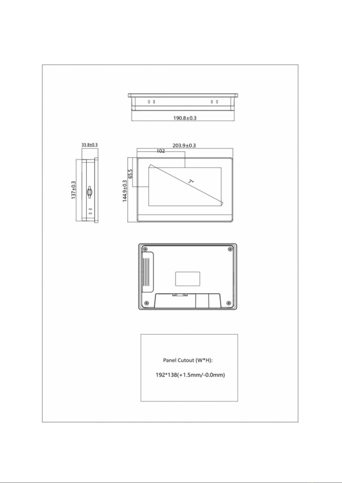
6.3 Mounting size ...............................................................................7
6.4 Fixed installation of structure........................................................8
7. Wiring.................................................................................................9
7.1 Power connection .........................................................................9
7.2 Communication connection..........................................................9
8. Program Interface Description..........................................................12
8.1 Home page..................................................................................12
8.2 menu ..........................................................................................13
8.3 Alarm ..........................................................................................13
8.4 Input/output 1 ............................................................................14
8.5 Input/output 2 ............................................................................15
8.6 Temperature humidity curve.......................................................16
8.7 Pressure curve ............................................................................16
8.8 User Settings...............................................................................17
8.9 Basic setting................................................................................18
8.10 Many setting .............................................................................19
8.11 Alarm setting ............................................................................19
8.12 User change password ..............................................................20
8.13 User password confirmation .....................................................21

3
1. Overview
DN-97335 is a IIoT human-machine interface. It is high-quality and cost-effective
touch screen, industrial ABS plastic shell, low cost, high reliability. The main
board is treated with a special coating (three anti-paint) to adapt to harsh
environments.
DN-97335 IoT HMI, features a 7" resistive touchscreen, 800x480 resolution,
24-bit colors, high-performance CPU, 4GB storage, and IoT module supported.
2. Appearance
3. Package Content
•1x Touch screen with integrated metal plate and wiring
•1x User Manual

4
4. Specifications
Hardware
parameter
Display 7” 16:9 TFT LCD
Resolution (W x H) 800×480
Colors 24-bit
Brightness 360 cd/m²
Backlight LED
LCD Life 50000 hours
Touch Panel 4 wires resistive touch screen
CPU 600MHz ARM Cortex-A8
Memory 128M Flash + 128M DDR3
RTC Built in
Ethernet NA
USB Port
USB Slave 2.0 port x1,
USB Host 2.0 port x1
Download Project USB Slave/ U-disk
COM Port
COM1:RS232/RS485/RS422
COM3:RS232
LCD viewing angle
(T/B/L/R)
50'/ 70'/ 70'/ 70'
Electrical
Specifications
Power Consumption < 10W
Input Power DC24V, working range DC 9V~28V
Power Protection
Protected from thunderstrike and
surging
Power Down Allowed < 5mS
Environment
Specifications
Operating Temperature 0~50℃
Storage Temperature -20~60℃
Anti-UV
Not suitable to work in strong
ultraviolet light
(such as direct sunlight)
Operating Humidity 10~90%RH (No condensation)
Vibration Endurance
10~25Hz
(X, Y, Z direction 2G/30 minutes)

5
Cooling method Natural air cooling
Mechanical
Index
Degree of Protection
Front IP65 (with NEMA panel),
Back IP20
Enclosure Engineering plastic
Panel Cutout (W x H) 192 × 138 mm
Dimension 204 × 145× 33.8 mm
Weight About 560g
5. Interface definition
Power terminal DB9 Serial port USB Host USB slave
Power terminal (Pin1~Pin3from left to right)
Pin1 FG
Pin2 0V
Pin3 DC24V
DB9 Serial terminal
Pin1 Rx- (B)
Pin2 RxD
(COM1 RS232)
Pin3 TxD (COM1 RS232)
Pin4 Tx-
Pin5 GND
Pin6 Rx+(A)
Pin7 RxD
(COM3 RS232)
Pin8 TxD (COM3 RS232)
Pin9 Tx+

6
USB Host
USB Type A Used to connect U disk, scan
code gun and other peripherals
USB Slave
MicroUSB
Used to download programs
and debug
IIoT Expanding Module
Connection
Expansion
module card
slot (Option)
Application for network
connection
6. Install
6.1 Installation precautions
Please ensure that AC power cords, PLC output modules, contactor starters, and
other types of electrical interface equipment are kept at a distance from the back
of the device product when installing the device behind this product.
6.2 Installation procedures
Embed the appliance on the operating panel of the control cabinet and install
the metal snaps with a crosshead screwdriver and a random panel. Follow these
steps to install.
•On the panel surface, cut a rectangular mounting groove and open the
embedded holes according to the opening size, then embed the HMI host
from the front of the panel.
•Insert the metal tabs in the top and bottom four mounting jack positions
on the back of the HMI console, insert the fixing screws (included) and
tighten them with a cross screwdriver.

7
6.3 Mounting size

8
6.4 Fixed installation of structure
Install the display assembly on the U column of the cabinet and fix it with crown
screws and nuts. A total of 4 screws are required to be fixed.

9
7. Wiring
7.1 Power connection
Hold the screen touch panel anywhere and power up the HMI to 24V DC.
7.2 Communication connection
Connection of the unit DN-97330/ DN-97331
(a). Display port
Bottom of DN-97330/ DN-97331
D is p la y
B
ABA-+PE
Monitor

10
(b). Connect to the display.
Connection port of the unit DN-97332/DN-97333/ DN-97334:
(a): Display port
Back of DN-97332/DN-97333
Table des matières
Autres manuels Digitus Moniteur


