transponding example presented here will show you how to set up 4 transpond-
ing zones each with 4 detection sections using one BDL16 & one RX4. For
most layouts, this set up will be just what is needed. If your plan calls for
other capabilities, instructions for more advanced options are also available.
Before you begin planning and wiring your layout for transponding, you may
want to set up a test transponder as described in Section 8.6 of this manual.
This will help you become familiar with the concepts involved in setting up
transponding and will be a useful de-bug tool as you proceed with the actual
installation on your layout.
3.2 Advanced Transponding
The combination of BDL16 & RX4 and the addition of other LocoNet compo-
nents like the PM4 offer many additional possibilities for detection &
transponding that are not be presented in this manual. Please visit our web site
www.digitrax.com Application Notes and Technical Information page to print
out additional ideas and examples for advanced transponding & detection. If
you are not able to find these documents on the web site, our tech support staff
will be happy to mail or fax copies to you upon request.
4.0 BDL16 Installation
The BDL16 is used to host your RX4. It provides the LocoNet connection
and wiring connections you will need to set up the layout for feedback. Before
installing your RX4, you will need to have a BDL16 installed. The manual
that came with your BDL16 will guide you through how to do this and how to
troubleshoot problems with the BDL16.
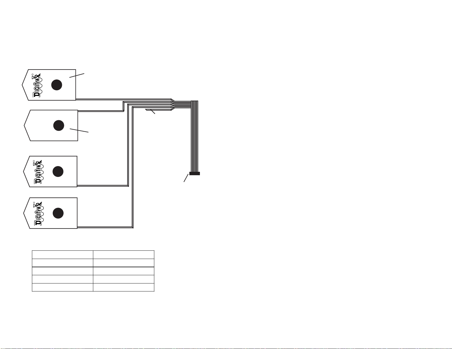
5.0 The RX4
Each RX4 is made up of 4 RX1 sensors, a ribbon cable and a connector that
let’s you plug the unit into a BDL16. The RX1’s are very sensitive to current.
The detection level is sensitive enough that reliable detection & transponding
can be achieved with transponding current levels of only 1-2% of the zone cur-
rent. In most cases, a level of 20-30 milliamps is enough for dependable oper-
ation. For example, on a N-scale board decoder, the 470ohm dropping resistor
that comes installed on the board is enough current for a zone of 2-3 amps.
See Section 7.0 for more information about enabling your transponder
equipped decoders for transponding.
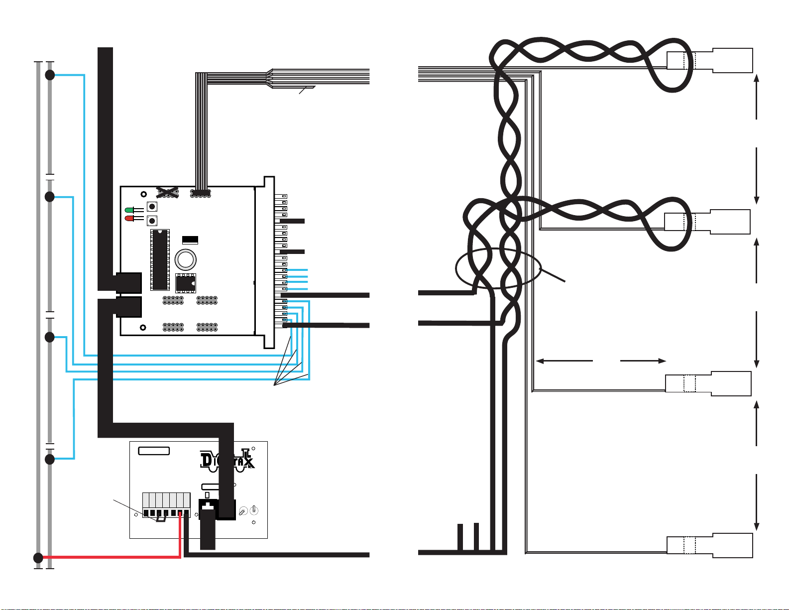
Because of the high sensitivity level of the RX1’s their placement relative to
the zone common wires is important to avoid interference among the RX1’s
installed on the layout. Follow the spacing instructions carefully to be sure you
have the best operation possible.
5
nected to an occupancy detector so that the detector can sense the presence of a
loco (or other specially equipped cars) in that section of track.
Occupancy detector is a device that senses the presence of a locomotive (or
other specially equipped cars) in a section of track that is set up for occupancy
detection. Occupancy detectors also provide feedback to indicate occupancy.
This feedback may be in the form of a lamp on a control panel or it may be a
feedback message sent to the system that can be used by other layout devices.
Also called a block occupancy detector on conventional layouts. Detectors are
not covered by the DCC Standards or Recommended Practices.
Transponder is an electronic device with a transponder address that is
installed in rolling stock. Transponders provide information to transponder
detectors installed on the layout. This lets the system determine in which
transponder zone the transponder is currently located. Transponders are includ-
ed in many Digitrax premium decoders. TD1 (transponder) & TL1 (transpon-
der with light output) are available as separate units that can be added to locos
with existing decoders or to other rolling stock without decoders if you want to
use them for transponding only and don't need motor control.
Transponder detector is an electronic device installed in a detection section
on the layout that receives the information broadcast from a transponder. The
transponder detector sends feedback to the system that lets it determine the
detection section location of any given transponder at any time. RX4
Transponder detectors are hosted by the BDL16 and upgrade 4 detection zones
of the BDL16 to be transponder detection zones. In this case, each transpond-
ing zone encompasses 4 detection zones.
Transponder zone is an area of track that may be single gapped on one rail or
double gapped on both ends and equipped with a transponder detector. Up to
four detection sections can be included in a transponder zone.
3.0 Plan Your Feedback System
Before you begin installing BDL16’s & RX4’s you should carefully analyze
your layout and what you want to achieve with your feedback system. The
best choice is usually a combination of detection sections and transponding
zones. To use transponding effectively, you do not need to set up transponding
on every section of track. By using transponding and other types of detection
technologies in tandem, you will be able to get excellent performance and
results at the lowest possible cost.
3.1 Basic Transponding
This manual presents basic transponding & detection wiring. The zone
4