1. Description of the EC500 Motion Controller Device:
For firstly of all we thank you for your interesting in our product and for reading this user’s guide.
The EC500 is a high-performace external motion controller for Mach3, with ethernet interface,supporting
standard MPG pendant.The device can communicate with a connection to a control computer’s network.The
network connection can be built with direct connection or via router/Swith devices.
The computer connects to the EC500 via a standard Ethernet cable.The cable may be shielded or unshield-
ed.An advantage of the Ethernet compared to a USB is that the cable length maybe as long as 100 meters.The
maximum length for a USB cable is 5 meters,and that is pushing it in a noisy working environment.Another
advantages is that Ethernet uses transformers for coupling the data signals,which galvanically isolates the
computer from the downstream electronics.
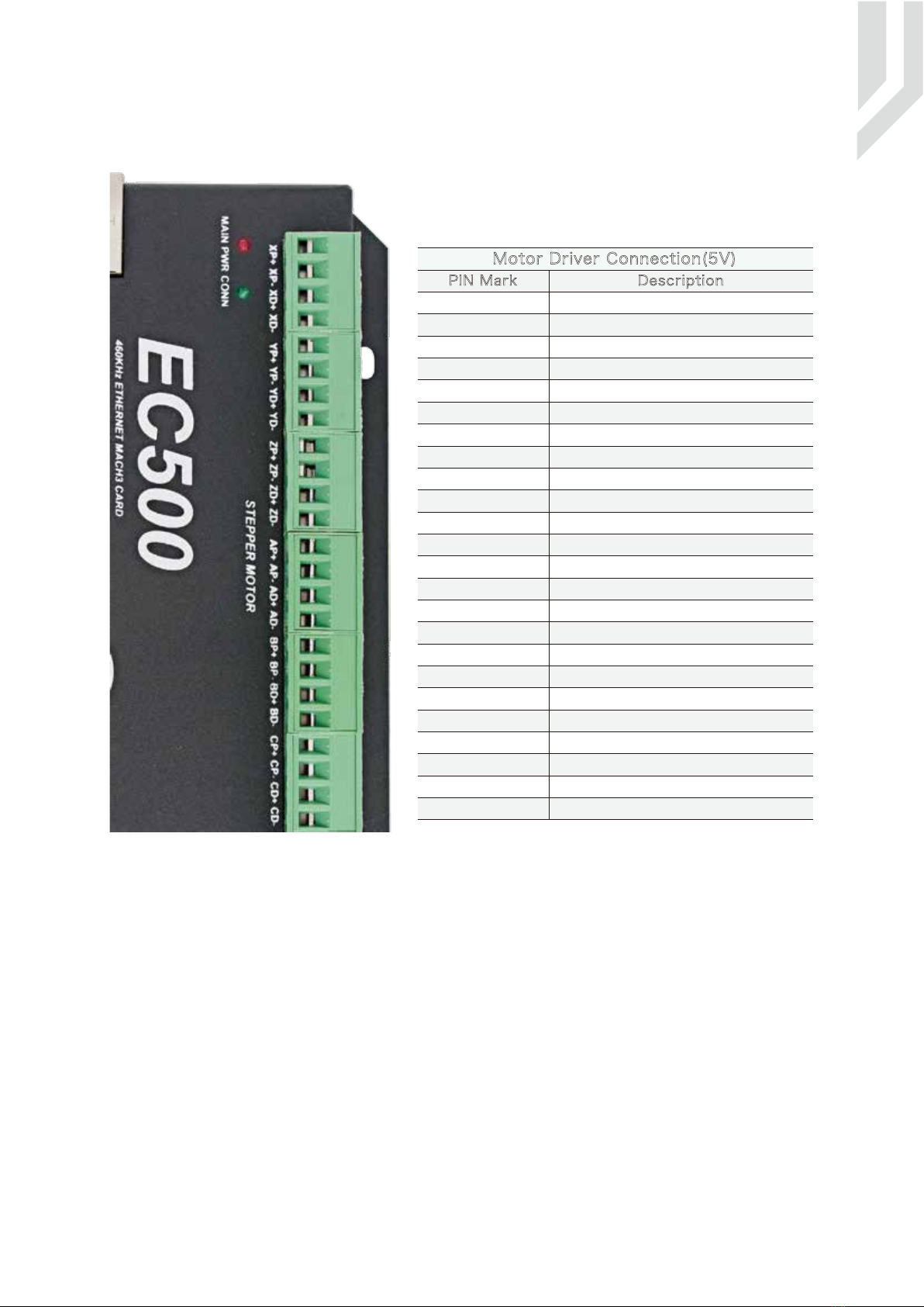
The device can be used to control machine tools with stepper or servo motor controls with pulse and direc-
tion interfaces;the controller can output a maximum of 460kHz stepping frequency for each axes and can work
with upto 6-axes.The Controller is 3-6 Axis for user’s options.
This user’s guide describes how to establish connection between the device and controler computer,the
device and stepper/Servo drives and spindle motor,how to setup the LAN network and the device for the
communication.This document also describs the inputs and outputs,the electrical parameters and properties of
the motion controller.It guides the users how to run the device with Mach3 software,and how to set the parame-
ters in the software.
Here is the brief description for the device:
1) Motion control 3-6 Axis(X,Y,Z,A,B,C) for option,max frequency output 460Khz/Axis;
2) Main power supply 24VDC,Current should higher than 1A;
3) IO Power is 24VDC power supply input,current should higher than 1A;
4) IO Power is 24VDC power supply input,current should higher than 1A. (By the IO power supply,system
already supply the power for IO ports.So no need the external power supply for IO port anymore.);
5) 18 opto-isolated digital input ports,16 opto-isolated digital output ports;
6) 1 analog output port of 0-10V adjustable speed for spindle (can change to PWM output port);
7) ARM motion control chip;
8) Compatible with Standard MPG and also Digital Dream MPG
Accessories:
Beside the main products,in our package,there are accesories:1pcs 1.5meter Ethernet cable.
2. Safety Notes:
Moving objets like machine tool axes and automatical equipments can be very dangerous.Always make
sure to keep all machines safety standards.Always install E-stop switches and the required safety equipments to
your control system and make sure that the equipment controlled by our device meets all the safety standards.
Always keep the controller dry and away from falling chips and dust,protect the device from taint
damage.Avoid conneciton mistakes,avoid high voltage damage,avoid operation errors.
Protect the device from direct intensive sunshine beams and from extreme temperature levels and from
extra high humidity weather.
We cannot take the responsibility for any persernal injury and financial loss caused by any device failure
or caused by following an error in this documentation.
Page -1Digital Dream Mach3 Motion Controller EC500 User’s Manual