DigiPos WD-2049 Manuel utilisateur

Vacuum Fluorescent
Customer Display
MODEL: WD-2049
Version: 1.14

WD-2049 customer display
1
INDEX
1. FEATURES.........................................................................................................3
2. GENERAL SPECIFICATIONS.........................................................................4
3. UNPACKING AND CHECKING THE PARTS................................................5
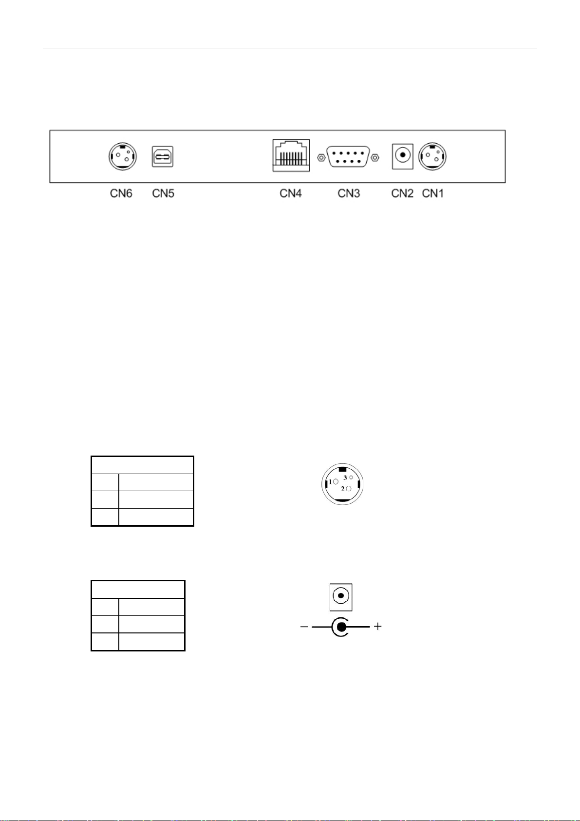
4. BASE PCB INTERFACE...................................................................................6
4.1 RS-232 INTERFACE CONNECTOR (ON THE BOTTOM OF THE BASE SECTION) ..........6
4.2 POWER SUPPLY CONNECTORS............................................................................6
4.3 CN5 /TYPE:DB25/F TOGETHER WITH SIGNALS OF RS-232C..............................6
4.4 RS232C LINK TO PC/HOST CONNECTOR (CN5).................................................7
4.5 RS232C LINK TO PRINTER CONNECTOR (CN3)....................................................7
4.6 RS232C LINK TO DISPLAY PANEL (CN4)............................................................7
5. USB BASE INTERFACE ...................................................................................8
5.1 USB INTERFACE CONNECTOR (ON THE BOTTOM OF THE BASE SECTION)...............8
5.2 POWER SUPPLY CONNECTORS............................................................................8
5.3 USB INPUT PORT LINK TO PC/HOST USB CONNECTOR (CN5)............................9
5.4 RS232C LINK TO PRINTER CONNECTOR (CN3)....................................................9
5.5 RS232C LINK TO DISPLAY PANEL (CN4)............................................................9
6. DIP SWITCH SETTING..................................................................................10
6.1 COMMAND TYPE SELECTION ............................................................................10
6.2 BAUD RATE SELECTION....................................................................................10
6.3 PARITY CHECK SELECTION...............................................................................10
6.4 INTERNATIONAL CHARACTER SET SELECTION ...................................................11
6.5 SELF-TEST &DEMO FUNCTION SELECTION........................................................11
7. COMMAND......................................................................................................12
7.1 CD5220 STANDARD MODE COMMAND LIST.....................................................12
7.2 EPSON ESC/POS COMMAND LIST .....................................................................15
8. CHARACTER SET ..........................................................................................18
8.1 USA, STANDARD CHARACTER SET (20H –7EH) ................................................18
8.2 INTERNATIONAL CHARACTER SETS..................................................................19
8.3 PAGE 0(PC437: USA, STANDARD EUROPE)(80H –FFH) ................................20
8.4 PAGE 1(KATAKANA)(80H –FFH)..................................................................21
8.5 PAGE 2(PC850: MULTILINGUAL)(80H –FFH)................................................22
8.6 PAGE 3(PC860: PORTUGUESE)(80H –FFH) ...................................................23
8.7 PAGE 4(PC863: CANADIAN-FRENCH)(80H –FFH) .........................................24
8.8 PAGE 5(PC865: NORDIC)(80H –FFH) ...........................................................25
8.9 PAGE 6(SLAVONIC)(80H –FFH)....................................................................26
8.10 PAGE 7(RUSSIA)(80H –FFH) ......................................................................27
8.11 PAGE 19 (PC858 EURO)(80H –FFH)............................................................28
8.12 PAGE 16 (WPC1252) (80H –FFH)................................................................29
8.13 PAGE 12 (GREEK)(80H –FFH) .....................................................................30

WD-2049 customer display
2
APPENDIX A: CUSTOMER DISPLAY DIMENSION ......................................31
APPENDIX B: DISPLAY BASE DIMENSION ..................................................31
APPENDIX C: DISPLAY MODULE DIMENSION ...........................................32
APPENDIX D: BASE ASSEMBLING.................................................................33
APPENDIX E: PASS THROUGH INSTALLATION GUIDE............................34

WD-2049 customer display
3
1. FEATURES
1. Data can be displayed on 20 columns x 4 lines.
2. Blue-green color and large character are easy to eye.
3. The display panel is adjustable to provide the best view angle.
4. Provide 2 poles for base position installation.
5. The DIP-switches setting emulate commands mode, baud rate and
international characters.
6. CD5220/EscPOS emulation command sets.
7. User-defined characters can be downloaded ( for EscPOS /CD5220
command).
8. Display area can be controlled by window function ( for EscPOS
command only).
9. Provides an interface based on RS-232C, and RS232C baud rate
from 9600 to 115200 bps.
10. Provides pass through function, so both printer and display can be
connected to the same port (ref. Appendix E).
11. Multi power connectable and wide range power input (+9 – +35 VDC).

WD-2049 customer display
4
2. GENERAL SPECIFICATIONS
NO ITEM Descriptions
1 Display method VFD display (blue green)
2 Number of character 20 columns x 4 lines
3 Brightness 500 cd/m2
4 Character type 5 x 7 dot matrix
5 Character size 9.0 x 5.25mm
6 Font 96 alphanumeric 13 international
1 user define 11 code page
7 Command and driver ESC/POS and OPOS
8 MTBF 25,000 hours
9 View angle 0 ~ 45 degree
10 Rotate angle 270 degrees (Max.)
11 Power supply +9 ~ +35 VDC
12 Power Consumption 6W (Max.)
13 Interface RS-232C and USB
14 Gross weight 1.8 Kg
15 Operating temperature 0 ~ 45℃
16 Operating Humidity 10 ~ 90 %RH
17 Storage Temperature -10 ~ 50℃
18 Storage Humidity 10 ~ 90 %RH
Table 2-1

WD-2049 customer display
5
3. UNPACKING AND CHECKING THE PARTS
Parts list:
(1) Display Module.
(2) Nut.
(3) Knob.
(4) Neck.
(5) Display Cable.
(6) Long Pole
(7) Short Pole
(8) Base Housing.
(9) Base PCB.
(10) Power Adapter (optional)
(11) AC Cord.
(12) RS-232C Cable.
(13) Plate
(1)
(4)
(3)
(6)
(7)
(8)
(10)
(9)
(12)
(2)
(13)
(11)
(5)

WD-2049 customer display
6
4. Base PCB Interface
4.1 RS-232 Interface connector (On the bottom of the base
section)
CN1,CN6: 24VDC power supply pass-through connects
CN2: Power input connector from adapter
CN3: RS-232C connect to printer
CN4: Connect to display panel
CN5: RS-232C connect to PC/Host
4.2 Power Supply Connectors
The variable power input which are available on base connectors, but only
if one connector can be selected for power input, the description as below:
4.2.1 CN2 / Type: DC jack (5.5/2.1)
Pin assignment
No Signal
+ Vin1
- GND
Table 4-1
4.2.2 CN1,CN6 / Type: Miniature jacks quick lock 3 pin
Table 4-2
4.3 CN5 / Type: DB25/F together with signals of RS-232C
Table 4-3
Pin assignment
No Signal
1 Vin2
2 GND
Pin assignment
No Signal
16,25 Vin3
7 GND

WD-2049 customer display
7
4.4 RS232C link to PC/HOST connector (CN5)
Type: DB25/F
Pin assignment
No Signal Direction Function description
2 TXD From printer to PC/Host Printer status data
3 RXD From PC/Host to display Receive data
4,20 DTR From display to PC/Host Display/printer ready signal
6 DSR From PC/Host to printer PC/Host ready signal
7 GND - Signal ground
16,25 Vin3 From PC/Host to display Power input
Table 4-4
4.5 RS232C link to printer connector (CN3)
Type: DB9/M
Pin assignment
No Signal Direction Function description
2 RXD From printer to PC/Host Printer status data
3 TXD From display to printer Printing data
5 GND - Signal ground
4,7 DTR From PC/Host to printer PC/Host ready signal
6 DSR From printer to display Printer ready signal
9 Vin2 From Hosiden to printer Power through to printer
Table 4-5
4.6 RS232C link to display panel (CN4)
Type: RJ45/8P/8C
Pin assignment
No Signal Direction Function description
1,2 Vin - Power 5VDC or 9~45 VDC
3,4 GND - Signal ground
5 DSR From Printer to Display Printer ready signal
6 DTR From Display to PC/Host Display/Printer ready signal
7 RXD From PC/Host to Display Display/Printing data signal
8 TXD From Display to Printer Printer status data signal
Table 4-6

WD-2049 customer display
8
5. USB BASE INTERFACE
5.1 USB Interface connector (On the bottom of the base section)
CN1,CN6: 24VDC power supply pass-through connects
CN2: Power input connector from adapter
CN3: RS-232C connect to printer
CN4: Connect to display panel
CN5: USB input
5.2 Power Supply Connectors
There are variable power inputs which are available on base connector,
but only one connector can be selected for power input function, the
description as below:
5.2.1 CN1,CN6 / Type: Miniature jacks quick lock 3 pin
Pin assignment
No Signal
1 Vin2
2 GND
Table 5-1
5.2.2 CN2 / Type: DC jack (5.5/2.1)
Pin assignment
No Signal
+ Vin1
- GND
Table 5-2

WD-2049 customer display
9
5.3 USB input port link to PC/HOST USB connector (CN5)
Type: USB Pin assignment
No Signal Direction Function description
1 V+ 5V From PC/Host USB power 5 VDC
2 D- Data signal -
3 D+ Data signal+
4 GND - Signal ground
Table 5-3
5.4 RS232C link to printer connector (CN3)
Type: DB9/M Pin assignment
No Signal Direction Function description
2 RXD From printer to PC/Host Printer status data
3 TXD From display to printer Printing data
5 GND - Signal ground
4,7 DTR From PC/Host to printer PC/Host ready signal
6 DSR From printer to display Printer ready signal
9 Vin2 From Hosiden to printer Power through to printer
Table 5-4
5.5 RS232C link to display panel (CN4)
Type: RJ45/8P/8C Pin assignment
No Signal Direction Function description
1,2 Vin - Power 5VDC or 9~45 VDC
3,4 GND - Signal ground
5 DSR From Printer to Display Printer ready signal
6 DTR From Display to PC/Host Display/Printer ready signal
7 RXD From PC/Host to Display Display/Printing data signal
8 TXD From Display to Printer Printer status data signal
Table 5-5
Table des matières
Autres manuels DigiPos Moniteur


