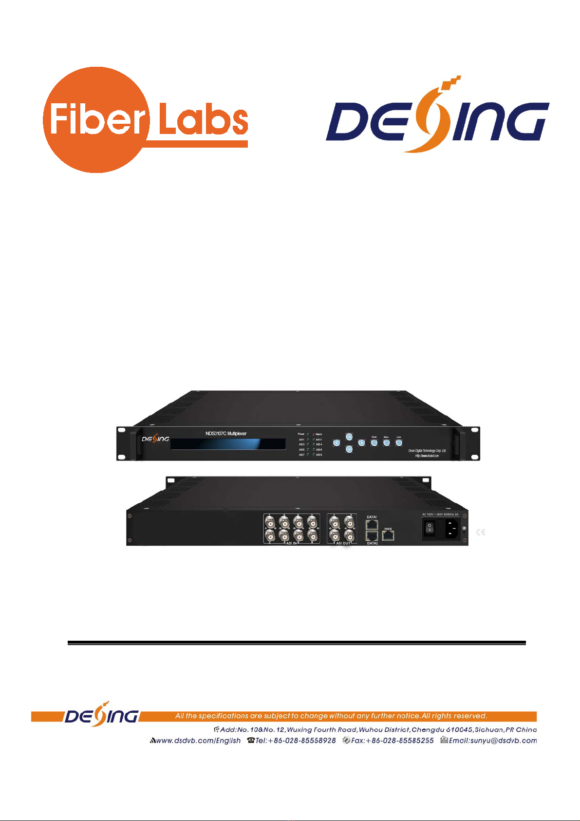
Dexing FiberLabs NDS3107C Manuel utilisateur

NDS3107C Multiplexer
User’s Manual
Dexin Digital Technology Corp. Ltd.

NDS3107C Multiplexer User Manual
DIRECTORY
CHAPTER 1 PRODUCT OUTLINE......................................................1
1.1 OUTLINE ...............................................................................................1
1.2 FEATURES.............................................................................................1
1.3 SPECIFICATIONS...............................................................................1
1.4 PRINCIPLE CHART...........................................................................2
1.5 APPEARANCE AND DESCRIPTION.............................................2
CHAPTER 2 INSTALLATION GUIDE.................................................4
2.1 ACQUISITION CHECK.....................................................................4
2.2 INSTALLATION PREPARATION...................................................4
2.3 WIRE’S CONNECTION.....................................................................6
2.4 SIGNAL CABLE CONNECTION....................................................6
CHAPTER 3 OPERATION.......................................................................8
3.1 LCD MENU............................................................................................8
3.2 INITIAL STATUS .................................................................................9
3.3 GENERAL SETTINGS........................................................................9
CHAPTER 4 WEB NMS OPERATION.............................................. 13
CHAPTER 5 TROUBLE SHOOTING................................................ 20
CHAPTER 6 PACKING LIST............................................................... 21

NDS3107C Multiplexer User Manual
1
Chapter 1 Product Outline
1.1 Outline
NDS3107Cmultiplexer is an enhanced TS re-multiplexer for digital TV broadcasting
head-end system. It can multiplex up to 8 ASI and 512 IP input and output TS through 2
groups of separate ASI output port and two GE port for two separate IP outputs. The
multiplexer has all the functions of normal TS multiplexer, including programs
multiplexing, PID re-mapping etc. Also the multiplexer can insert EPG (Electronic Program
Guide), and data casting information into each output stream. In conclusion, its high
integration and cost effective design make this device widely used in the CATV
Broadcasting system.
1.2 Features
Fully complying with ISO13818 and EN300 468 standard
Support 8 ASI input for re-multiplexing
Support 512 IP input through DATA1 and DATA2 over UDP protocol
Support accurate PCR adjusting/ PID re-mapping/PSI/SI rebuilding and editing
Two groups (each group has 2 channels)separate ASI outputs
IP (2 MPTS) over UDP, RTP/RTSP output as mirror of ASI output (RJ45), GE Port,
DATA1 and DATA 2
Huge buffer memory for saving the overflowing code stream
Support to multiplex one program to all outputs
LCD/keyboard and Web-based NMS management
1.3 Specifications
Input 8 ASI input+512 IP input DATA 1 and DATA 2 over UDP protocol
PID re-mapping
PCR accurate adjusting
Re-multiplex
PSI/SI (PAT, PMT) tables auto generation and edition
ASI 2 groups separate outputs (each group has 2
channels)
Output port
IP MPTS over UDP, RTP/RTSP output (RJ45),
1000Mbps Ethernet, DATA 1 and DATA 2
Output range 0x0000—0x1FFFPID
PID transparent Any PID transparent and mapping achievable

NDS3107C Multiplexer User Manual
Amount of output
PID 180
NMS port Ethernet port 10/100M/1000M self adaption
Dimensions 482mm×300mm×44mm (WxLxH)
Weight 3.5kg
Temperature 0~45℃(operation), -20~80℃(storage)
General
Power supply AC 110V±10%, 50/60Hz Or AC 220V±10%,
50/60Hz
1.4 Principle Chart
1.5 Appearance and Description
Front panel Illustration:
1 2 3 4 5 6
Indicator area: All the indicators will light on when NDS3107C multiplexer works at its current
mode.
1 LCD Display
Power Indicator
Alarm Indicator
2 ASI 1~ASI 8: when the input signal of ASI is locked, the light is green.
Otherwise it becomes red.
2

NDS3107C Multiplexer User Manual
3 UP/ DOWN /LEFT/RIGHT Key
4 Enter: Confirmation key
5 MENU Key
6 LOCK Key
Rear panel Illustration:
3
7 8 9 1011 12
7 ASI IN1~8: TS input
ASI OUT 1: TS output
ASI OUT 2: TS output ( as mirror of ASI 1)
ASI OUT 3: TS output
8
ASI OUT 4: TS output( as mirror of ASI 3)
9 NMS Ethernet Port ( 10/100/1000Mbps)
10 Data port: two Gigabits IP outputs port
11 Power switch, fuse, socket
12 Grounding pole

NDS3107C Multiplexer User Manual
Chapter 2 Installation Guide
2.1 Acquisition Check
When user opens the package of the device, it is necessary to check items according to packing
list. Normally it should include the following items:
NDS3107C Multiplexer
User’s Manual
ASI Cable
Power Cord
If any item is missing or mismatching with the list above, please contact local dealer.
2.2 Installation Preparation
When users install device, please follow the below steps. The details of installation will be
described at the rest part of this chapter. Users can also refer rear panel chart during the
installation.
The main content of this chapter includes:
Checking the possible device missing or damage during the transportation
Preparing relevant environment for installation
Installing multiplexer
Connecting signal cables
Connecting communication port (if it is necessary)
2.2.1 Device’s Installation Flow Chart Illustrated as following:
2.2.2 Environment Requirement
Item Requirement
Machine Hall Space When user installs machine frame array in one machine hall, the
distance between 2 rows of machine frames should be 1.2~1.5m
4

NDS3107C Multiplexer User Manual
5
and the distance against wall should be no less than 0.8m.
Machine Hall Floor
Electric Isolation, Dust Free
Volume resistivity of ground anti-static material:
1X10⁷~1X10¹⁰,Grounding current limiting resistance: 1M
(Floor bearing should be greater than 450Kg/㎡)
Environment
Temperature
5~40℃(sustainable ),0~45℃(short time),
installing air-conditioning is recommended
Relative Humidity 20%~80% sustainable 10%~90% short time
Pressure 86~105KPa
Door & Window Installing rubber strip for sealing door-gaps and dual level glasses
for window
Wall It can be covered with wallpaper, or brightness less paint.
Fire Protection Fire alarm system and extinguisher
Power
Requiring device power, air-conditioning power and lighting
power are independent to each other. Device power requires AC
power 220V 50Hz. Please carefully check before running.
2.2.3 Grounding Requirement
All function modules’ good grounding is the basis of reliability and stability of devices. Also,
they are the most important guarantee of lightning arresting and interference rejection.
Therefore, the system must follow this rule.
ASI cable’s outer conductor and isolation layer should keep proper electric conducting with
the metal housing of device.
Grounding conductor must adopt copper conductor in order to reduce high frequency
impedance, and the grounding wire must be as thick and short as possible.
Users should make sure the 2 ends of grounding wire well electric conducted and be antirust.
It is prohibited to use any other device as part of grounding electric circuit
The area of the conduction between grounding wire and device’s frame should be no less
than 25mm2.
2.2.4 Frame Grounding
All the machine frames should be connected with protective copper strip. The grounding wire
should be as short as possible and avoid circling. The area of the conduction between grounding

NDS3107C Multiplexer User Manual
6
wire and grounding strip should be no less than 25mm2.
2.2.5 Device Grounding
Connecting the device’s grounding rod to frame’s grounding pole with copper wire.
2.3 Wire’s Connection
The grounding wire conductive screw is located at the right end of rear panel, and the power
switch, fuse, power supply socket is just beside ,whose order goes like this, power switch is on
the left ,power supply socket is on the right and the fuse is just between them.
Connecting Power Cord
User can insert one end into power supply socket, while insert the other end to AC power.
Connecting Grounding Wire
When the device is solely connected to protective ground, it should adopt independent way,
say, share the same ground with other devices. When the device adopts united way, the
grounding resistance should be smaller than 1Ω.
Caution:
Before connecting power cord to NDS3107C multiplexer, user should set the power switch
to “OFF”.
2.4 Signal Cable Connection
The signal connections include the connection of input signal cable and the connection of
output signal cable. The details are as follows:
2.4.1 ASI In and ASI out connection:
ASI Input Connection
User can find ASI input port on the device according to connector mark described in the rear
panel illustration, and then connect the ASI cable (in the accessories). One end is connected to
the Multiplexer’s ASI input port, while the other end is connected to Encoder’s ASI output port
or ASI output port of other equipment.
ASI Output Connection

NDS3107C Multiplexer User Manual
User can find ASI output port on the device according to connector mark described in the rear
panel illustration, and then connect the ASI cable (in the accessories); one end is connected to the
Multiplexer’s ASI output port and the other end to the Modulator’s ASI input port or ASI input
of other equipment. Multiplexer’s ASI cable illustrated as follows:
2.4.2 Network cable (Category 5) illustration:
7

NDS3107C Multiplexer User Manual
Chapter 3 Operation
NDS3107C multiplexer’s front panel is user operation interface. The detailed operations go as
follows:
Keyboard Function Description:
MENU: Canceling presently entered value, resuming previous setting; Return to previous menu.
ENTER: Activating the parameters which need modifications, or confirming the change after
modification.
LEFT/RIGHT: To choose and set the parameters.
UP/DOWN: Modifying activated parameter or paging up/down when parameter is inactivated.
LOCK: Locking the screen / canceling the lock state. After pressing lock key, the system will
question the users to save present setting or not. If not, the LCD will display the current
configuration state.
At the page of 5.2 “Load default CFG”, user can firstly press “ENTER” key, consequently
system resumes factory parameter setting.
3.1 LCD Menu
An overview of the LCD menus:
Initializing
Current General
Working Status
1 Status 1.1 Uptime
2 TS Config 2.1 Out 1
PMT Interval
SDT Interval
SDT Insert
Packet Mode
Out Bit Rate
Original Net ID
Transport Stream
Same contents as Out 1
1.2 Alarm
2.1 Out 2
PAT Interval
8
Table des matières
Manuels Multiplexeur populaires d'autres marques

ADTRAN
ADTRAN Frameport 768 Manuel utilisateur

Elo TouchSystems
Elo TouchSystems E247 Manuel utilisateur

Paradyne
Paradyne Hotwire 8786 Manuel utilisateur

RFL Electronics
RFL Electronics 9508D UCC Manuel utilisateur

Miranda
Miranda AMX-101i Mode d’emploi

ShipModul
ShipModul MiniPlex-AIX NMEA-0183 Manuel utilisateur