desiree DTPP609 Manuel utilisateur
1
Simple Parking Lift Manual
MODEL:DTPP609

2
Catalogue
1.Introduce................................................................................................................ 3
1.1 Summarize..................................................................................................... 3
1.2 Statement....................................................................................................... 3
2. Equipment introduction...........................................................................................4
2.1 Equipment description.............................................................................. 4
2.2 Equipment parameter...................................................................................4
3.Equipment transportation........................................................................................4
4.Assemble the lift ..................................................................................................... 5
4.1 Notice.............................................................................................................. 5
4.2Layout of the equipment ............................................................................. 6
4.3Tools for installing equipment:.................................................................. 7
4.4Installation procedure:................................................................................ 7
5.Introduction of control system..............................................................................22
5.1 Control principle.......................................................................................... 22
5.2Control issues that need attention............................................................ 22
5.3Control problem ..........................................................................................23
6.Electrical schematic............................................................................................... 24
7.Hydraulic schematic...............................................................................................24
8.Precautions for use................................................................................................ 25
8.1Announcements........................................................................................... 25
8.2 Parking cars.................................................................................................25
8.3 Take cars .................................................................................................... 26
9.Equipment maintenance....................................................................................... 26

3
1.Introduce
1.1 Summarize
The DTPP609 is a two-column hydraulic parking system. This manual should be read carefully
before installing and assembling equipment, which helps to assemble and use the equipment in the
right way to avoid risks and increase the reliability and service life of the equipment.
The operator should follow the instructions in this manual, otherwise the user will be
responsible for any loss and personal injury.
1.2 Statement
The operator shall operate the equipment in accordance with the instructions of the user manual
and the operator shall be responsible for any loss or personal injury.
If your equipment is damaged during transportation, the carrier shall be liable.
The equipment you purchase is safe in the first place of design and production, but to further
ensure safe use, equipment operators must be professionally trained and highly responsible. Do
not operate and service the equipment until you have read this manual thoroughly and without
carefully checking the safety of this equipment.
This warranty is the ultimate quality assurance of the product ,Product damage caused by bad
weather, natural disasters, damage during transportation, and failure to properly inspect the
maintenance is not covered by this warranty.

4
2.Equipment introduction
2.1 Equipment description
The DTPP609 is a hydraulic parking lift with three parking spaces for two parking plates.
This lift has the advantages of simple structure, convenient assembly and space saving, and is
well received by users. This lift is mainly composed of two side columns and a wave plate
platform.
2.2 Equipment parameter
Drive mode: cylinder drive
Maximum size of suitable vehicles: (can choose the size of the equipment)
(L×W×H)Ground Level :5200×2100×1900mm
Second Level:5000×2050×1550mm
Third level:5000×1950×1550mm
Maximum weight can parking:2000kg
Single equipment area: 12 square meters
3.Equipment transportation
Carefully remove the equipment and parts box. Note: When cutting the strap, the device may
be loose, so prevent the device from falling and hurting people.
Check the equipment for damage during transportation and whether it is short. Remember: If
the equipment is missing, it should be indicated on the relevant documents to prove whether it
is lost on the way to the transporter or the company is missing.

5
4.Assemble the lift
4.1 Notice
4.1.1 Read and understand the equipemt's safety alerts before using the equipment.
4.1.2 Pay attention to protect your hands and feet. The hands and feet must be removed from
the rotating parts. When the equipment falls, remove the feet to avoid being crushed.
4.1.3 Keeping the work site neat, clean, and chaotic workplaces can cause injury.
4.1.4Check the working environment of the equipment, do not expose the equipment to rain, do
not use the equipment in a humid environment, and the equipment area must be well ventilated
and illuminated.
4.1.5 This equipment should only be used by trained personnel. All untrained personnel should
stay away from the work area and do not allow untrained personnel to access and use the
equipment.
4.1.6 Use the quipment in the right way. Please do not modify the equipment with parts not
supplied by the factory.
4.1.7 When lifting or dropping the car, keep away from the working area of the equipment.
4.1.8 If the car on the platform is in a dangerous state, there must be enough shelter space.
4.1.9 Prevent electric shocks. In order to protect the operator, the grounding wire of the
equipment motor must be grounded reliably and must not be connected to other objects.
4.1.10 Warning! The power unit voltage on the equipment is very high. The power must be cut
off before servicing the electrical equipment on the power unit.。
4.1.11 Pay attention to maintenance. The equipment must be kept clean so that there is a safe
environment. Proper lubrication and maintenance contribute to the reliable use of the
equipment. Handle the machine carefully to prevent injury, especially to prevent it from being
crushed when the device is tipped over.
4.1.12Must keep a clear head. Be alert and alert when working.
4.1.13It is forbidden to remove any parts that involve safety.
4.1.14Maintain the safety locking device
4.1.15 When lifting the equipment, the guarantor is in a safe area.

6
4.1.16 Always check for damaged parts and check their activity and synchronization. If any
parts are not working properly, please do not use the equipment.
4.1.17 Warning! The work area should be non-flammable because there is an electric spark
when the switch is working.
4.2 Layout of the equipment
Before you install your lift, you should check the following items:
4.2.1 The work area should be designed and have enough space.
4.2.2 Avoid obstacles, such as the presence of wires in the installation area.
4.2.3 Carefully inspect the concrete floor where the equipment is to be installed for cracks and
check that the strength of the concrete meets the requirements. On the ground with a
compressive strength of not less than 25Mpa, the thickness of the ground concrete is not less
than 500mm, the number is not lower than C25, the newly poured concrete must be solidified
for at least 28 days, the ground error is not more than 3mm, and the expansion bolt size is
M19*160. Otherwise, the equipment will destroy the ground, which will cause damage to the
equipment and casualties.
4.2.4 The installation of the ground must ensure a certain level. The limit cannot exceed 5 mm.
Within this limit, it can be adjusted by a spacer. If the ground is severely uneven, it should be
repaired.
4.2.5 Installation of equipment on sloping floors or other non-concrete floors is prohibited.
4.2.6 It is forbidden to install equipment on cracked ground or inferior concrete floors.
4.2.7 Installation of equipment on the second floor or above is prohibited without the approval
of the architect.
4.2.8 If there is no protective measure, please do not install the equipment outdoors to avoid
damage to the motor in rainy weather.
4.2.9 Determine where the equipment is installed, then place the column and the platfrom in
their respective positions. Place the platfrom between the two columns
4.2.10 Confirm the position of the electrical control box and leave enough room for operation.
4.2.11 After confirming, draw the position of the bottom plate of the column with chalk to
ensure the error within 3mm, so as to avoid affecting the installation of the equipment.。
4.2.12 Check carefully to make sure the layout is correct。
7
4.3 Tools for installing equipment
Hammer, level, open end wrench, hex wrench, adjustable wrench, crowbar, chalk or colored
pen, flat head screwdriver, tape measure (5 m), needle-nosed pliers, etc.
4.4 Installation procedure :
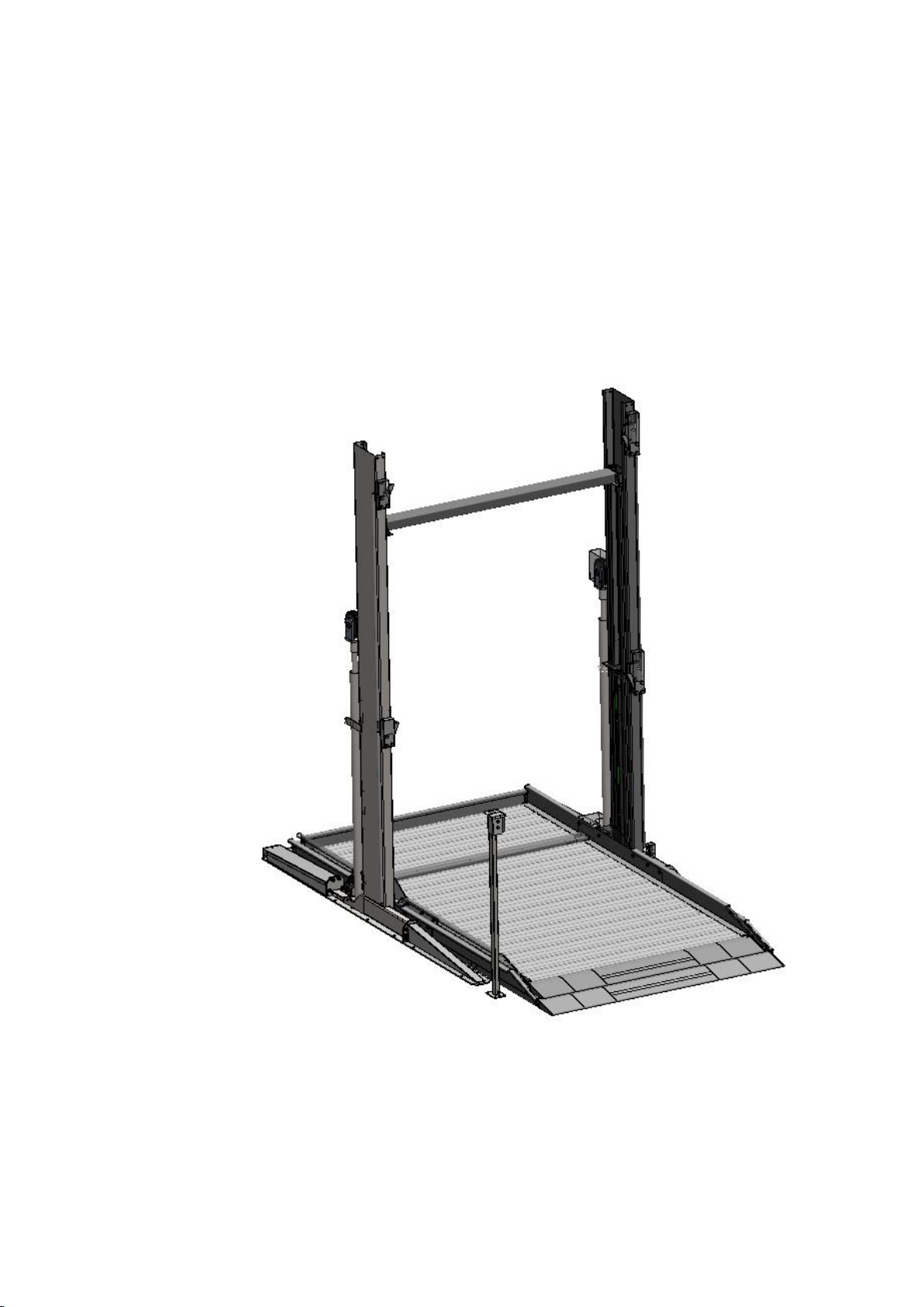
FIG1 .Down position schematic
8
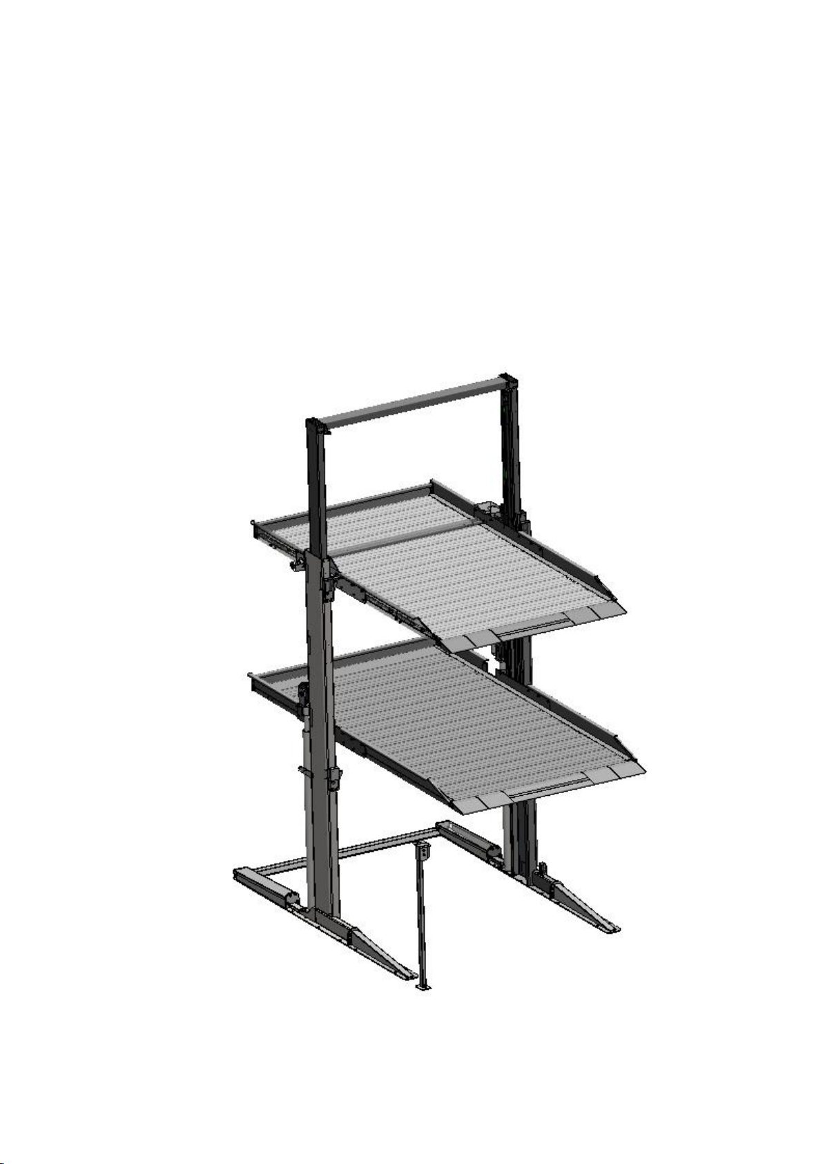
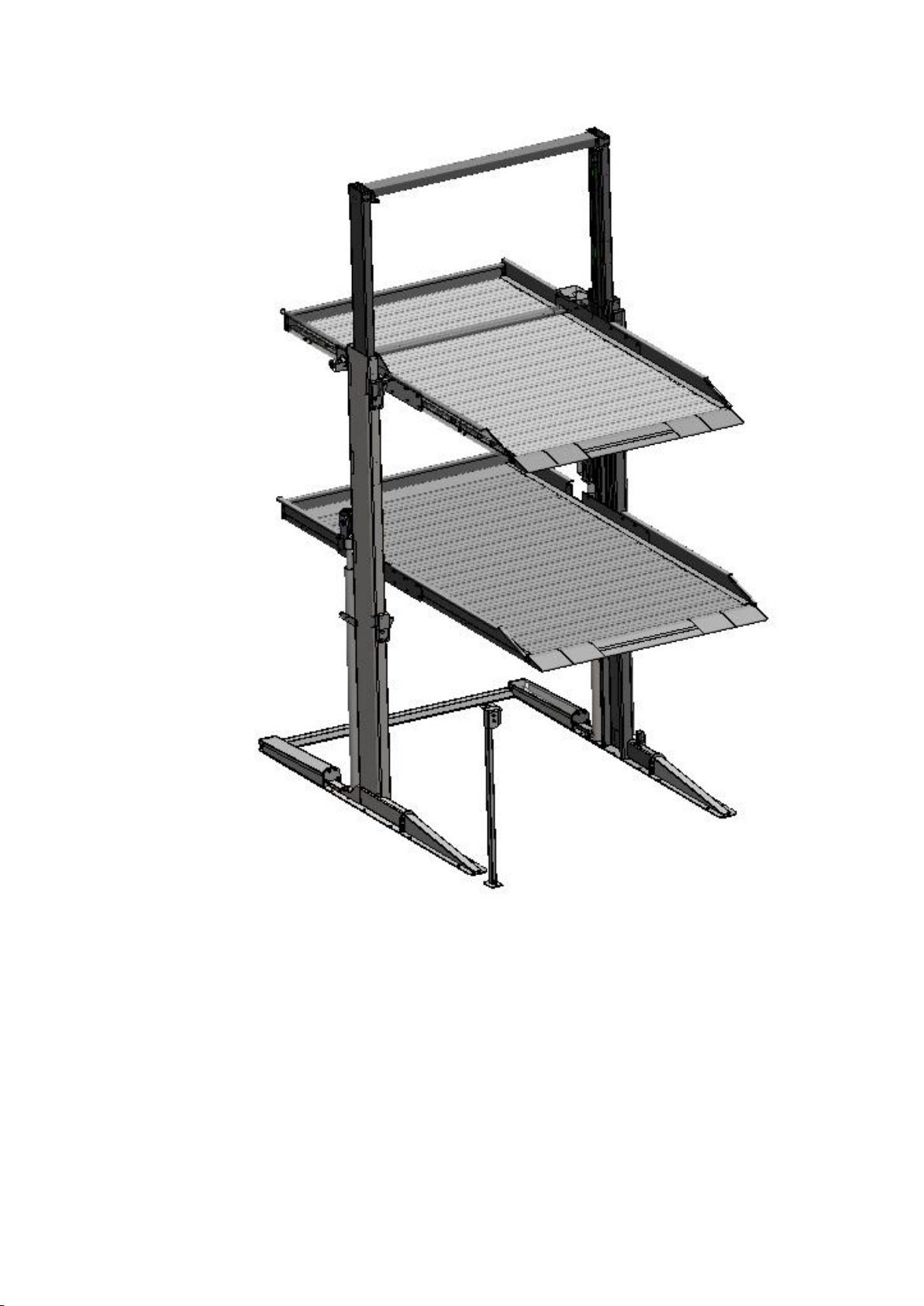
FIG2 Up position schematic
9
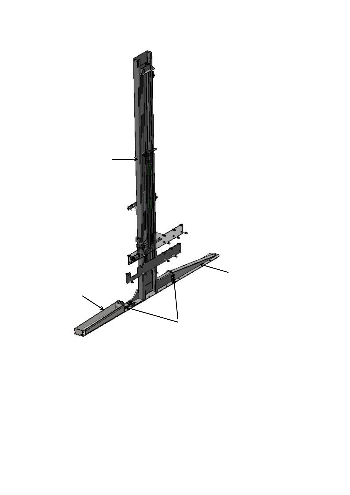
4.4.1Column front leg and additional plate install
FIG 3 Column front leg and additional plate installation diagram
4.4.2 Move the Stage 1 and Stage 2 carriage to the distance shown in Figure 4 and support
them with wooden or steel tubes of appropriate height to prevent the carriage from
falling.
additional plate
Front leg
Column
M16*50outer hexagon bolt 10pcs
M16 nut 10pcs
Ø16 plain washers 10pcs
Ø16 spring washer 10 pcs

10
FIG4 Cariage movement diagram
4.4.3Foundation diagram
FIG 5 Foundation diagram
Stage 1 carriage
Stage 2 carriage
500m
1000
Table des matières


