Designs for Vision LED DayLite Micro Manuel utilisateur

LED DayLite®
Micro
User Guide
Ver. 10.17

2
LED DAYLITE®MICRO USER GUIDE
CONTENTS
Indications for Use.........................................................4
Device Description.........................................................4
Device Diagrams ............................................................5
Directions for Use..........................................................7
Charging the Battery .................................................6
Using the Headlight...................................................9
Understanding the Status Indicator ........................10
Holster Operation....................................................12
Inspection and Preventative Maintenance .................13
Important Safety Instructions......................................14
Plug Adapter Kit...........................................................16
Specifications...............................................................17
Description of Various Symbols...................................18
Warranty......................................................................18

3
LED DAYLITE®MICROUSER GUIDE
INDICATIONS FOR USE
The Designs for Vision®LED DayLite®Micro is a lightweight,
frame-mounted headlight that is designed for general
illumination in laboratory settings.
DEVICE DESCRIPTION
The Designs for Vision® LED DayLite® Micro provides bright,
portable light to the laboratory environment. The headlight
is designed to clip onto a wide variety of frames. It is
powered by a lithium ion battery and generates a 3” spot of
light at a 12-inch working distance. The light has a correlated
color temperature of 5800K and a maximum intensity of
60,000 lux. The unit can run on battery power for up to 10
hours before needing to be recharged.
The LED DayLite® Micro consists of the following:
Two Power Packs
HDi™Micro Headlight
UV/Blue Light Filter (installed)
Two Holsters
Belt Clip

4
LED DAYLITE®MICRO USER GUIDE
USB Power Supply
Headlight Cable
USB Power Cord
Hex Drivers (2)
T-Mount Bracket (sold separately)
Operation Manual
Registration Card
Cable Wrap Kit
Always examine the unit and accessories for damage before
commencing use. Damaged accessories must not be used
and must be replaced. Use original Designs for Vision, Inc.
parts and accessories only. The use of unapproved parts may
void the warranty.
DEVICE DIAGRAMS
Your LED DayLite® Micro is designed to be simple and
lightweight. It consists of an HDi™ Micro Headlight, Power
Pack, and USB Power Supply. NOTE: The UV/blue light filter
comes attached to the HDi™ Micro Headlight, but is
removable. The following diagram identifies each part for
your reference in this manual:

5
LED DAYLITE®MICROUSER GUIDE
STATUS INDICATOR
HDi™MICRO
HEADLIGHT
CHARGER PORT
HEADLIGHT
PORT
POWER -
LIGHT
INTENSITY
BUTTON
UV/ BLUE
LIGHT FILTER
POWER PACK
USB POWER SUPPLY
CHARGER
PORT
FIG.1
6
LED DAYLITE®MICRO USER GUIDE
NOTE: The batteries
need to receive a
full charge before
initial operation
DIRECTIONS FOR USE
CHARGING THE BATTERY
Remove the components from the shipping container,
checking that all parts on the packing list have been
received. Carefully remove the
headlight, power packs, USB
power supply and USB power
cord from the packaging carton.
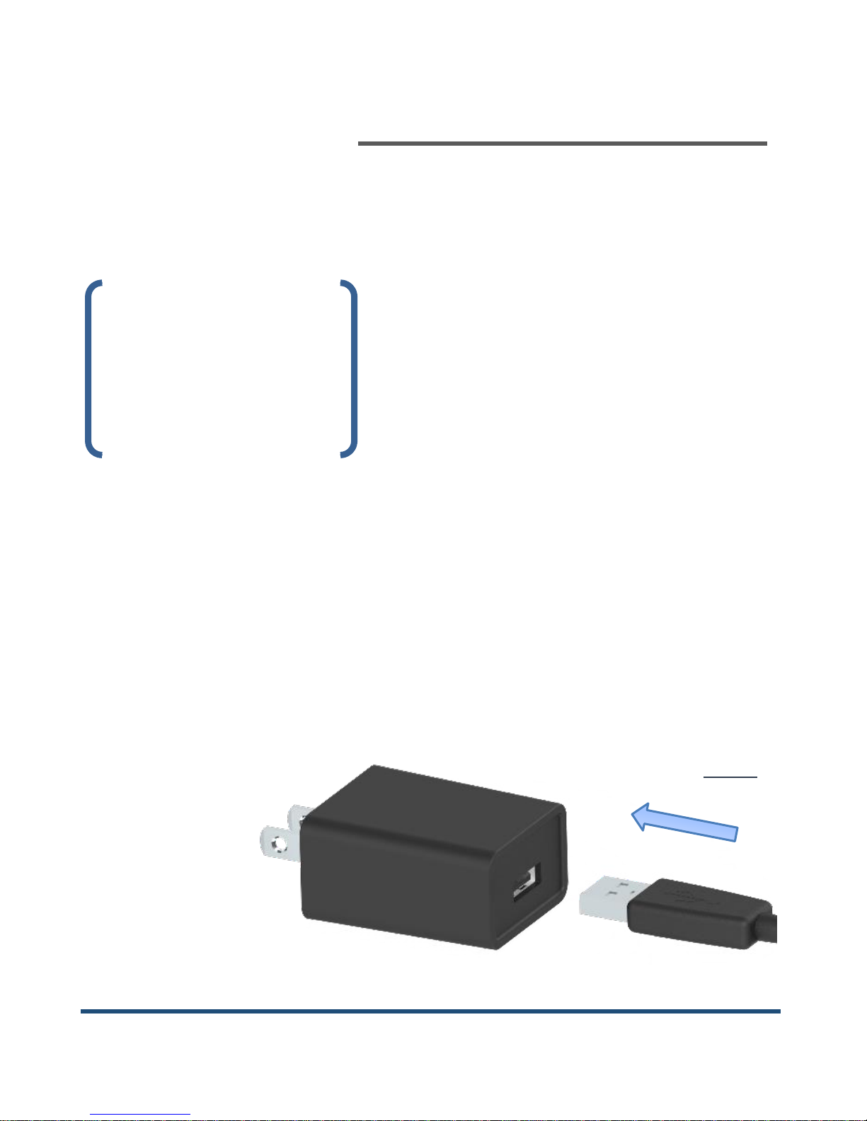
The USB power supply is designed to meet multi-national
regulatory requirements and has multi-input voltage
capability to accommodate various line voltages from 100-
240 VAC. The power packs can be charged from any
standard 5V USB output however, it is recommended that
they are
charged with
the supplied
USB power
supply for
FIG.2

7
LED DAYLITE®MICROUSER GUIDE
CHARGER PORT
STATUS INDICATOR
optimal charge times.
Plug the large end of the USB power cord into the charger
port of the USB power supply (Fig. 2).
Connect to an available AC
outlet. NOTE: International
adapters are
available
through
Designs for
Vision; refer
to the list on page 16. Plug the small end of
the power cord into the charger port on
the power pack (Fig. 3).
NOTE: The connectors only fit in one
direction. Do not force together.
The power button light will start pulsing
to indicate the unit is in “Smart Charge”
mode. The status indicator (Fig. 3) will
FIG.4
FIG.3

8
LED DAYLITE®MICRO USER GUIDE
display the current state of charge. The LED will change
colors as the battery charges; going from RED to ORANGE to
GREEN. When the power button light remains steady, the
unit is fully charged. You can now disconnect the power cord
from the power pack.
USING THE HEADLIGHT
Place the HDi™ Micro headlight onto the t-mount bracket
for your frame. Connect the small end of the headlight cable
to the headlight. Connect the large end of the headlight
cable to the headlight port on the top of the power pack.
The headlight can be adjusted up and down to align with
your point of view.
The headlight can
then be locked into
that position using
the provided driver.
Locate the hex in the locking shaft of the headlight (Fig. 5).
Place the driver into this opening and turn clockwise to
FIG.5

9
LED DAYLITE®MICROUSER GUIDE
tighten the shaft. To unlock the position, loosen the shaft by
turning counter-clockwise.
NOTE: The shaft will only turn a limited distance. Do not
force in either direction.
Press the power button on the front of your battery pack.
The headlight will turn on at high intensity. The power
button will illuminate and the status indicator will display
the current state of charge. A second press of the power
button will lower the light intensity of the headlight. A third
press turns the power pack off.
The LED DayLite® Micro also incorporates a Low Battery
Warning system. With approximately ten (10) minutes of
battery power remaining, the headlight will flash three
times. At five (5) minutes remaining, the headlight will flash
another three times. At 30 (thirty) seconds remaining, the
headlight will flash continually until the battery is
completely depleted.

10
LED DAYLITE®MICRO USER GUIDE
A UV/blue light filter is
provided to prevent
premature curing of
dental composites
(comes pre-installed).
To use, slide the filter
over the front of the headlight until completely seated (Fig.
6). Using the supplied tool, tighten the set screw on the
bottom of the filter to properly secure to the headlight. You
can now rotate the UV/blue light filter into and out of the
path of light, as required.
NOTE: Be careful to not overtighten set screw when
installing.
UNDERSTANDING THE STATUS INDICATOR
The LED DayLite® Micro incorporates an advanced status
monitoring system. The following table describes what each
indication signifies:
FIG.6
Table des matières
Autres manuels Designs for Vision Lampe de poche


