DeLOCK 63110 Manuel utilisateur

Product-No:63110
User manual no:63110-a
www.delock.com
Cable Tester RJ45 / PoE / DC
User manual
Bedienungsanleitung

-2-
English
Description
With this cable tester by Delock the wiremap of network cables
can be tested quickly and easily. The results are shown clearly on
the illuminated LCD display. The remote unit can be used to test
already installed cables.
PoE and DC measurement
The PoE standard and the used wire pairs of a PoE voltage source
can be determined. With a connected load, the actual voltage,
polarity, current and power are displayed in real time.
Specication
• Matrix LCD display with background lighting
• 6 operating buttons
• Display of open, short or crossed connections
• Display of used PoE standards 802.3af or 802.3at
• Display of used PoE pairs (12/36) or (45/78)
• Display of voltage, polarity, amperage and power for PoE or DC
• Test range voltage: DC 0 - 60 V
• Test range current: 0 - 3 A
• Test range power: 0 - 180 W
• Auto power-o mode
• Flashlight function
System requirements
• 3 x AAA battery
Package content
• Network cable tester
• Remote unit
• Bag
• User manual
-3-
English
Safety instructions
• Protect the product against moisture
• Protect the product against direct sunlight
• If the product is not used for a long time, take out the batteries.
• Never use the product to detect electrical power circuits (220V).
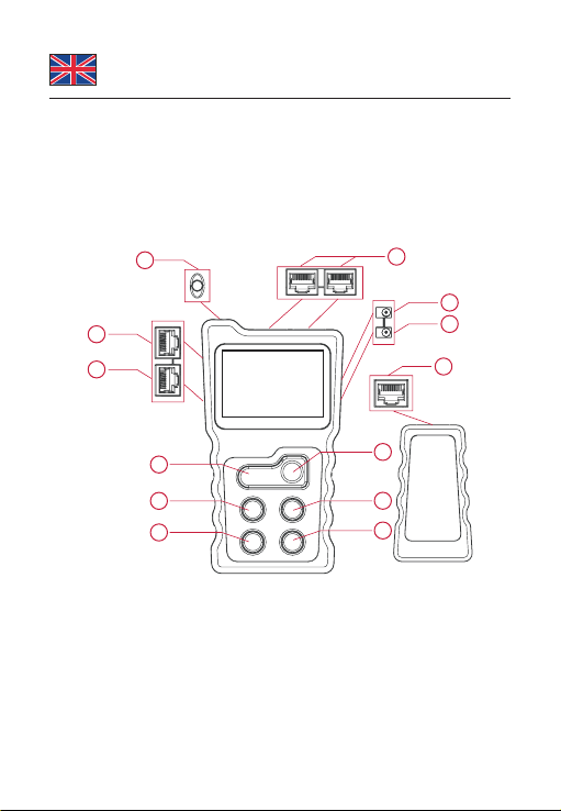
Overview
10
1
2
3
4
5
9
6
12
11
7
8
13
1. Lamp 6. Power 11. Right
2. PoE test 7. DC In 12. OK
3. Loopback 8. DC Out 13. RJ45
4. RJ45 Wiremap 9. Left
5. Light 10. Return

-4-
English
Main Menu
(1) PoE PoE switch test and PoE power test
(2) CONT Test RJ45 for continuity
(3) Power Test voltage, current and power of a powered
device.
(4) LOOP Loop-back switch test
(5) SET Setup backlight, auto power o, and contrast.
Turn on the tester, and navigate by pressing the LEFT, RIGHT,
BACK and OK buttons.
POE
CONT
P
UI
POWERLOOPSET
PoE switch test
The PoE Tester allows to test live Ethernet cable and to determine
if power and data are present. It also identies the type of Power
Sourcing Equipment (PSE).
Connect one end of a LAN cable into the PoE / RJ45 port of the
tester, and the other end into the port of the PoE switch. Turn on the
PoE equipment.
After a correct connection, a voltage value will show on the screen.
Now press "OK" to start testing.
12345678
PoEMidspan
+534VDC 12W
Pins
providingpower
Mode
s
power
Polarity
Voltage

-5-
English
The screen will display the results:
- Pins providing power
- Mode (Endspan, Midspan)
- PSE type (Standard or NonStandard)
- Polarity and Voltage
If the connection is not correct, the display will show "Connect
Error" or "Unconnected". After reconnecting correctly, you can test
again.
PoE power test
In PoE power test mode, a PoE power supply device (PoE switch)
and a PoE powered device (PoE camera) can be connected to the
tester (PoE ports).
After a correct connection, a voltage value will show on the screen.
A few seconds later, and it will automatically enter the power testing
interface. When the screen is displaying PoE power, press the OK
key to identify the type of PSE.
The screen will display the results:
- Pins providing power
- Mode (Endspan, Midspan)
- PSE type (Standard or NonStandard)
- Polarity and Voltage
- Power (power currently consumed by the PoE powered device)
Wire mapping test
The Cable Tester can test twisted pair cables and will identify wrong
connections, short circuit and open circuit.
Connect one end of a LAN cable into the RJ45 port of the main unit,
and the other end into the remote unit of the tester.

-6-
English
CONT
R : 1 2 3 4 5 6 7 8
M : 1 2 3 4 5 6 7 8
R : 1 2 3 4 5 6 7 8G
M : 1 2 3 4 5 6 7 8G
8pins9pins
CONT
If the cable is OK, you will see test results like above.
R :
M : 1 2 3 4 5 6 7 8
Short
CONT
R : 1 2 3 4X6 7X
M : 1 2 3 4X6 7X
CONT
R : 1 2 3 4 5 6 7 8
M : 1 2 3 4 5 6 7 8
CONT
If the cable is not OK, you will see test results like above.
Short mapping: There is a short circuit between 2 wires. If there is
short, cross, open status at the same time, only short circuit will be
displayed, no other status.
If the wires are not connected, the display will show the open
connection.
If the wires are crossed, the display will show the connection
problems indicated by an X.
If the cable or the remote unit is not connected, the tester will show
"Cable Open".

-7-
English
Power Test Function
This can test voltage, current and power between the power
adapter and the powered device. Connect the tester between the
DC power adapter and the device, choose "Power" at the menu,
then the results will display immediately as below.
POWER
Voltage 12 0V
Current 185A
Power22 2W
Loop-back Test
This part is to test if the loopback of the network cable connected to
a switch is working properly.
Connect the switch port to the loop-back port of the tester with a
network cable. If the indicator is on, it means the loop is OK. If the
indicator is o, it means that there are problems in the loop.
Flashlight Function
Press the "Light" button to turn the ashlight LED on or o.
Setting
a. Backlight setting
Adjust the backlight active time between 15s, 30s, 60s, always on,
or o.
b. Auto-o time
Adjust the device power-o time between 15min, 30min, 1h, OFF.
c. Contrast setting
Press the left and right keys to adjust the contrast.

-8-
English
Support Delock
If you have further questions, please contact our customer support
You can nd current product information on our homepage:
www.delock.com
Final clause
Information and data contained in this manual are subject to change
without notice in advance. Errors and misprints excepted.
Copyright
No part of this user manual may be reproduced, or transmitted
for any purpose, regardless in which way or by any means,
electronically or mechanically, without explicit written approval of
Delock.
Edition: 06/2020

-9-
Deutsch
Kurzbeschreibung
Mit diesem Kabeltester von Delock kann schnell und einfach die
Belegung von Netzwerkkabeln getestet werden. Die Ergebnisse
werden auf der beleuchteten LCD Anzeige übersichtlich dargestellt.
Zum Prüfen bereits verlegter Kabel kann die Remote-Einheit
verwendet werden.
PoE und DC Messung
Der PoE Standard und die verwendeten Adernpaare einer
PoE Spannungsquelle können bestimmt werden. Mit einem
angeschlossenen Verbraucher werden die aktuelle Spannung,
Polartität, Strom und Leistung in Echtzeit angezeigt.
Spezikation
• Matrix LCD Anzeige mit Hintergrundbeleuchtung
• 6 Bedientasten
• Anzeige von Unterbrechung, Kurzschluss, gekreuzten Adern
• Anzeige für verwendete PoE-Standards 802.3af oder 802.3at
• Anzeige für verwendete PoE Adernpaare (12/36) oder (45/78)
• Anzeige von Spannung, Polarität, Strom und Leistung für PoE
oder DC
• Prüfbereich Spannung: DC 0 - 60 V
• Prüfbereich Strom: 0 - 3 A
• Prüfbereich Leistung: 0 - 180 W
• Automatischer Power-o Modus
• Taschenlampen Funktion
Systemvoraussetzungen
• 3 x AAA Batterie
Packungsinhalt
• Netzwerk-Kabeltester
• Remote-Einheit, Tasche
• Bedienungsanleitung

-10-
Deutsch
Sicherheitshinweise
• Produkt vor Feuchtigkeit schützen
• Produkt vor direkter Sonneneinstrahlung schützen
• Wenn das Produkt längere Zeit nicht verwendet wird, entfernen
Sie bitte die Batterien.
• Verwenden Sie das Produkt nicht mit elektrischen Stromleitungen
(220V).
Übersicht
10
12
3
4
5
9
6
12
11
7
8
13
1. Lampe 6. Power 11. Rechts
2. PoE Test 7. DC In 12. OK
3. Loopback 8. DC Out 13. RJ45
4. RJ45 Wiremap 9. Links
5. Licht 10. Zurück
Table des matières
Langues :
Autres manuels DeLOCK Équipement de test


Manuels Équipement de test populaires d'autres marques

SMART
SMART KANAAD SBT XTREME 3G Series Manuel utilisateur

Agilent Technologies
Agilent Technologies BERT Serial Manuel utilisateur

Agilent Technologies
Agilent Technologies N3280A Manuel utilisateur

Vernier
Vernier Go Direct Voltage Manuel utilisateur

Lifeloc
Lifeloc R.A.D.A.R. Manuel utilisateur

Fluke
Fluke T5-600 Instructions d'utilisation et d'installation


