Deep Innovations PoolScout Manuel utilisateur


When using electrical equipment, basic safety precautions should always
be followed, including:
WARNING: Installation must be done by a trained, approved technician.
WARNING: Use only appropriate power adapter and cables as described
in this manual. Inappropriate cables and adapters may not work with your
camera and may cause damage.
WARNING: Disconnect power before servicing. There are no user
serviceable parts inside the camera or alarm.
WARNING: All power cords should be inspected frequently. Any damaged
power cords must be replaced immediately to reduce the risk of electric
shock.
WARNING: Install in accordance with local building and installation codes.
WARNING: Mount camera and alarm in a safe area not subject to damage
by moving objects.
WARNING: Keep camera and components out of reach of children and
pets.
WARNING: PoolScout is not a substitute for constant pool supervision by
a responsible adult. The PoolScout System, including any sensors, cameras,
software, and alarms are NOT a substitute for personal, adult supervision
of pool activities and pool patrons, or the pool safety measures required by
the Virginia Graeme Baker Pool & Spa Safety Act.
WARNING: When you place the PoolScout System in “Shut Down” mode,
the PoolScout System will NOT operate to accomplish the Purpose; and all
its pool safety functionality will be disabled and it will NOT work to detect
or warn you of any hazardous conditions associated with your Pool or any
Pool Patron.

• Internet with at least 5.0 Mbps upload speed
• Available ethernet port on the home network’s router
• A mobile device running the PoolScout app on at least iOS 12 or
Android 6.0 (available on the AppStore and Google Play)
• Power drill and drill bits
• Phillips head screwdriver and small at head screwdriver
• Caulk to seal Junction Box to mounting surface
• Router to be within 100 feet of mounting point.
• Camera should be placed such that the furthest point of the pool does
not exceed 50ft from the camera

4321
ALARM

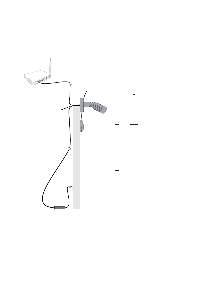
Before installation, give thought to a suitable mounting location and how
you will route wiring back to the Power Adapter and the home network’s
router.
The Camera must be mounted on an outside wall with power and Ethernet
brought to the Junction Box from indoors. The power supply will be
plugged into an indoor electrical socket as shown on page 4 and 6.
The ideal mounting height for the PoolScout Camera is 7-10 feet off of the
ground tilted downward. The Alarm Module must mount close enough to
the camera so that the Alarm Cable will reach.
Factor in an additional length that will be routed through the back of the
Alarm Module.
The nal mounting location should allow for a clear view of the entire pool
and surrounding area at all times. Do not allow anything such as
sunshades, basketball hoops or other pool side objects to block the
camera’s view, even temporarily.

• Should provide an unobstructed view of the pool and at least 6 feet of
the surrounding area
• Should be 7-10 feet off the ground
• Shouldn’t interfere with its surroundings or be vulnerable to damage
• Should be accessible from the inside of the exterior wall where the
PoolScout will be mounted
• Should allow for the 100 foot ethernet cable to be run from the home
network’s Router
• Should allow for the 100 foot power cable to be run from the power
adapter
• Should allow for the alarm module to be mounted less than 3 feet
away from the camera
If satised with the proposed mounting location, mark the spot.

1. Camera should be rotated to align with the horizon
2. Camera to tilt downward towards pool
3. Camera should view as much of the pool and surrounding area as
possible
The PoolScout Camera will fasten to the supplied Junction Box and its
mount has a fully articulating hinge. By loosening the locking screws, you
can rotate the mount and camera as shown in the diagram below. Loosen
the locking screws and roughly position the camera in its intended location
As shown above, an access hole may be needed to run the cables that will
power and communicate with the PoolScout system. An existing outdoor
opening may be considered if you can route the cables through from
indoors. If not, a hole will need to be drilled.
Use a ½” drill bit and make sure that there are no in-wall pipes or electrical
wires in the drill path. Before drilling, t the Junction Box over the
previously marked spot. Make sure that it can be centered over the hole
and properly fastened to the surface. Also, plan the orientation of the exit
tting and the mounting location of the Alarm Module before drilling.
Router

4321
ALARM
The connections shown below will be made inside of the Junction Box.
Refer to the diagram and the following sections in this manual:
After drilling the access hole, remove the Junction Box cover and rear
knockout. Center the box over the hole to test t. Position the exit tting
(used for Alarm Module wiring) where desired. When satised, spread
caulk around the outside back of the Junction Box, leaving a small space at
the bottom for water to run out. Fasten the Junction Box using the
included hardware. If the hardware is not suitable for the mounting
surface, use appropriate hardware purchased separately.
With the cover off, test t the Power Splitter cable inside of the Junction
Box and run the 4 conductor end of the Alarm Cable out of the Junction
Box exit tting. This should give you an estimate of where the Alarm
Module can be mounted (within approximately 3 feet of the camera).
Ce manuel convient aux modèles suivants
1
Table des matières
Manuels Système de sécurité populaires d'autres marques


EDM
EDM Solution 6+6 Wireless-AE Manuel utilisateur

Highway Safety Group
Highway Safety Group EA401 Manuel utilisateur

Siren
Siren LED GSM Manuel utilisateur

Detection Systems
Detection Systems 7090i Instructions de montage

Se-Kure Controls
Se-Kure Controls MicroMini SK-4841 Manuel utilisateur

Siemens
Siemens FDM273 Manuel utilisateur