DD Audio DSI-2 Manuel utilisateur

OWNER’S MANUAL
DSI-2

DD AUDIO / DSI-2 /1
Thank the you for purchasing the DD Audio DSI-2. The DSI-2 is a feature rich
audio signal processor that will allow you to precisely tune the acoustics of a
vehicle's audio system for maximum listening pleasure. It can be used in
conjunction with aftermarket systems or integrated into factory systems to realize
the full potential of the connected audio components. To ensure ease of use and
proper setup please take a moment to thoroughly read through this operation
manual. We hope you thoroughly enjoy this product, and if you have any
questions regarding the setup or installation please contact the DD Audio
technical support team.
INTRODUCTION

DESIGN FEATURES
• PC and Smartphone Graphic User Interfaces
• Customizable Parametric Equalizer, Crossovers, and Time Alignment
• Bluetooth Compatible (w/ optional BTR accessory package)
• Remote Controllable (w/ optional BTR accessory package)
• 6 Customizable EQ Presets
• 4ch High-level inputs
• 4ch Low-level RCA inputs
• Input Summing
• 10ch Low-level RCA outputs (8 Programmable + 2 Pass Through)
• Aluminum Chassis
DD AUDIO / DSI-2 /2

TECHNICAL SPECIFICATIONS
DD AUDIO / DSI-2 / 3
DSI-2
7.5V-17.5V
180Ω
20KΩ
≥50Ω
5V (CH1-CH8), 2.6V (CH9-CH10)
≥100dBA
≥105dBA
0.01%
0.002%
12V >500mA
8V
855mV
>10V(REM), >1.3V(SPK), >9mV(RCA)
3 Seconds
4
10 (8 DSP + 2 Pass Through)
10 Bands
24bit/48Khz
56bit
150 x 106 x 39
5.9 x 4.1 x 1.5
Operating Voltage
High-Level Input Impedance
RCA Input Impedance
RCA Output Impedance
RCA Output Voltage
High-Level Input S/N
RCA Input S/N
High-Level Input THD
RCA Input THD
REM OUT Output Current
SPK Input Sensitivity Max
RCA Input Sensitivity Max
Turn-On
Turn-On Time
Input Channels
Output Channels
Parametric EQ
Sampling Frequency
DSP Resolution
Dimensions mm (LxWxH)
Dimensions inches (LxWxH)

+12V:
Connect to 7.5V-17.5V constant positive power
supply input.
-GND:
Connect to a verified chassis ground.
Run a separate ground wire vs connecting it to a
factory ground wire. Factory ground wires
usually have multiple devices connected to them
and are not recommended because this can
lead to ground loop issues.
REM IN:
Connect to switched +12V turn-on power input.
REM OUT:
Provides a >500mA 12v switched
turn-on signal for connected amplifiers.
May require an additional relay for multi
amp turn-on.
IN1-IN4:
Connect to hi-level (speaker level) inputs for
integrating into OEM audio systems.
TURN-ON Switch:
Used to select the desired DSI-2 turn-on method.
REM=REM IN +12v, SPK=High level CH1-CH4
input (signal sense), RCA=RCA INPUT CH1-CH4
(signal sense).
PWR LED:
When illuminated indicates the unit is powered on.
BLUETOOTH:
Port for connecting the optional Bluetooth
interface dongle.
REMOTE:
Port for connecting the optional remote control via
modular cable.
PC CONTROL:
USB (type B) Port for connecting a PC to the
DSI-2 via USB Cable.
DD AUDIO / DSI-2 / 4
INPUT CONNECTION

RCA INPUT CH1-CH4:
Low-level inputs for connecting to a source unit
with low level RCA outputs.
RCA OUTPUT CH1-CH8:
DSP processed low-level analog signal outputs.
RCA OUTPUT CH9-10 (Pass Through):
Non DSP processed low-level analog
signal outputs.
DD AUDIO / DSI-2 / 5
OUTPUT CONNECTION
Accessing the interface:
1. Go to the DSI-2 product page at ddaudio.com for links to download the DSI-2 interface
software and apps. Install the DSI-2 app on a PC and/or smartphone.*
2. Connect the DSI-2’s PC Control Port to a computer using a USB cable, or link the DSP
to a smartphone via Bluetooth using the optional Bluetooth Dongle.
3. From the PC desktop or the smartphone app screen select the DSI-2 app icon.**
*Windows, Android, and iOS compatible
**When opening the DSI-2 app for the first time the computer may display a security warning stating the
publisher could not be verified. It is safe to run the DSI-2 application without causing any harm to
computer. Uncheck the “Always ask before opening this file” box to avoid this message in the future.

PC INTERFACE CONTROLS
DD AUDIO / DSI-2 / 6
CONTROL BAR:
•Memory: Use for saving, loading, and deleting
customized EQ settings.
•Options: Use to install software updates,
access available help menus, and to determine
the current software version.
•Encryption/Decryption: Use to password
protect, and unlock EQ presets.
•Connected/Not Connected: Indicates the
connection status between the interface
and DSI-2.
•Disconnect: Use to connect or disconnect the
interface to a DSI-2
AUDIO ADJUSTMENTS:
1. EQ Display: This window displays a visual
representation of the current EQ settings.
Click on an EQ band and set its center
frequency by dragging it to the desired
frequency. Adjustments can be made to the
Q Factor and dB Level of each EQ band from
this this window.
Input Signal Display : The input signal gain for
output channels CH1-CH8 can be adjusted
from this window. This window can be used to
sum input channels by adjusting the input
channel level.
See page 10 for detailed Output/Input
Configuration and Summing Instructions.
(NOTE) Use the Mixer button to switch between
the EQ Display and Input Signal Display.
2. Crossovers: From this window set the desired
crossover type, frequency, and crossover slope
for the selected EQ band.
a. Crossover Type: Choose the filter type
based on the equipment configuration and
design goals. Different types of filters
possess different phase alignment,
dampening, and Q factor characteristics.
b. High-pass filter: Evenly attenuates all
frequencies below the crossover frequency.
c. Low-pass filter: Evenly attenuates all
frequencies above the crossover frequency.
d. Crossover Slope (Filter Octave): Sets the
steepness/ rolloff rate of the filter when
either the low-pass or high-pass filter
is selected.
3. EQ Settings: From this window adjust the
center frequency, Q Factor, and dB level for
each EQ band.
a. PEQ Buttons: Activates Parametric
EQ filter setting capabilities for EQ Bands 1
and/or 10. A parametric EQ boosts or cuts a
range of frequencies around around a
center frequency. Each equalization band
has three controls:
b. Parametric EQ (PEQ): A parametric EQ
boosts or cuts a range of frequencies
around around a center frequency.
Each equalization band has three controls:
•Frequency: The center of the frequency
range to be cut or boosted.
•Gain (dB): The amount of boost or cut.
•Q Factor: The "sharpness" of the boost or
cut, higher Q, means a narrower range of
frequencies will be affected.
c. LS Button: Activates a Low Shelf filter for
EQ Band 1. A low shelf EQ filter has an
adjustable center frequency and will
boost/cut parameters below the center
frequency. Roll-off rate is selectable as 6dB
or 12dB per octave.
d. HS Button: Activates a High Shelf filter for
EQ Band 10. A high shelf EQ filter has an
adjustable center frequency and will
boost/cut parameters above the center
frequency. Roll-off rate is selectable as 6dB
or 12dB per octave.
e. Bypass EQ/Restore EQ Button: Allows
you to momentarily bypass then restore
EQ adjustments.
f. Reset EQ Button: Resets all EQ
adjustments.
4. Time Alignment Settings: To compensate for
various speaker locations and listening
positions, time delay adjustments can be made
to the output channels. By doing this you can
make every speaker's musical playback reach
the listener’s ears at the same time to create a
realistic, “concert-like” sound stage.
a. Graphically displays the selected output
channel via a highlighted speaker image and
allows you to input the amount of desired
delay for that channel.
b. Allows you to select the desired unit of
duration for the delay Milliseconds(Ms),
Centimeters(Cm), or Inches(In).
See page 9 for detailed Time Alignment
Instructions.
5. Main Volume: Adjusts the volume of all
outputs evenly.
6. Input/Output Channel Configuration: From
this window you can adjust the output dB level,
select the desired input channel/s, switch
phasing, mute, and link output level controls for
the selected output channel.
See page 10 for detailed Input/Output
Configuration and Summing Instructions.
7. EQ Display/Input Signal Button: Use this
button to switch the top window between the
EQ Display and Input Signal control panels.
1.
3.
5.
6.
2.
4a.
7.
4b.

CONTROL BAR:
•Memory: Use for saving, loading, and deleting
customized EQ settings.
•Options: Use to install software updates,
access available help menus, and to determine
the current software version.
•Encryption/Decryption: Use to password
protect, and unlock EQ presets.
•Connected/Not Connected: Indicates the
connection status between the interface
and DSI-2.
•Disconnect: Use to connect or disconnect the
interface to a DSI-2
AUDIO ADJUSTMENTS:
1. EQ Display: This window displays a visual
representation of the current EQ settings.
Click on an EQ band and set its center
frequency by dragging it to the desired
frequency. Adjustments can be made to the
Q Factor and dB Level of each EQ band from
this this window.
Input Signal Display : The input signal gain for
output channels CH1-CH8 can be adjusted
from this window. This window can be used to
sum input channels by adjusting the input
channel level.
See page 10 for detailed Output/Input
Configuration and Summing Instructions.
(NOTE) Use the Mixer button to switch between
the EQ Display and Input Signal Display.
2. Crossovers: From this window set the desired
crossover type, frequency, and crossover slope
for the selected EQ band.
a. Crossover Type: Choose the filter type
based on the equipment configuration and
design goals. Different types of filters
possess different phase alignment,
dampening, and Q factor characteristics.
b. High-pass filter: Evenly attenuates all
frequencies below the crossover frequency.
c. Low-pass filter: Evenly attenuates all
frequencies above the crossover frequency.
d. Crossover Slope (Filter Octave): Sets the
steepness/ rolloff rate of the filter when
either the low-pass or high-pass filter
is selected.
3. EQ Settings: From this window adjust the
center frequency, Q Factor, and dB level for
each EQ band.
a. PEQ Buttons: Activates Parametric
EQ filter setting capabilities for EQ Bands 1
and/or 10. A parametric EQ boosts or cuts a
range of frequencies around around a
center frequency. Each equalization band
has three controls:
b. Parametric EQ (PEQ): A parametric EQ
boosts or cuts a range of frequencies
around around a center frequency.
Each equalization band has three controls:
•Frequency: The center of the frequency
range to be cut or boosted.
•Gain (dB): The amount of boost or cut.
•Q Factor: The "sharpness" of the boost or
cut, higher Q, means a narrower range of
frequencies will be affected.
c. LS Button: Activates a Low Shelf filter for
EQ Band 1. A low shelf EQ filter has an
adjustable center frequency and will
boost/cut parameters below the center
frequency. Roll-off rate is selectable as 6dB
or 12dB per octave.
d. HS Button: Activates a High Shelf filter for
EQ Band 10. A high shelf EQ filter has an
adjustable center frequency and will
boost/cut parameters above the center
frequency. Roll-off rate is selectable as 6dB
or 12dB per octave.
e. Bypass EQ/Restore EQ Button: Allows
you to momentarily bypass then restore
EQ adjustments.
f. Reset EQ Button: Resets all EQ
adjustments.
4. Time Alignment Settings: To compensate for
various speaker locations and listening
positions, time delay adjustments can be made
to the output channels. By doing this you can
make every speaker's musical playback reach
the listener’s ears at the same time to create a
realistic, “concert-like” sound stage.
a. Graphically displays the selected output
channel via a highlighted speaker image and
allows you to input the amount of desired
delay for that channel.
b. Allows you to select the desired unit of
duration for the delay Milliseconds(Ms),
Centimeters(Cm), or Inches(In).
See page 9 for detailed Time Alignment
Instructions.
5. Main Volume: Adjusts the volume of all
outputs evenly.
6. Input/Output Channel Configuration: From
this window you can adjust the output dB level,
select the desired input channel/s, switch
phasing, mute, and link output level controls for
the selected output channel.
See page 10 for detailed Input/Output
Configuration and Summing Instructions.
7. EQ Display/Input Signal Button: Use this
button to switch the top window between the
EQ Display and Input Signal control panels.
DD AUDIO / DSI-2 / 7
PC INTERFACE CONTROLS (continued)
1.
Input Signal Display

1. Home Screen: Main Volume: Adjusts the
volume of all outputs evenly.
a. Encryption: Use to password protect and
unlock EQ presets.
b. Sound Selection: Allows the user to select
from the available presets.
c. Advanced Settings: Access the Time
Alignment, Equalizer, Output,
and Mixer screens.
2. Set Delay Screen: Select an output channel
and set the unit of duration and amount of
desired delay for each output channel when
time aligning the audio system. See page ? for
detailed Time Alignment Instructions.
3. Equalizer Screen: This screen displays a
visual representation of the current EQ settings
for the selected EQ band. Adjustments can be
made to the dB Level, Q Factor and center
frequency of each EQ band from this screen.
a. Bypass EQ/Restore EQ Button: Allows
you to momentarily bypass and restore
EQ adjustments
b. Reset EQ Button: Resets all EQ
adjustments
4. Output Screen: Adjust the output dB level,
switch phasing, mute, and link output level
controls for the selected output channel from
this screen. This is also the screen where you
can store and name customized EQ presets.
5. Mixer Screen: The input signal gain for output
channels CH1-CH8 can be adjusted from this
screen. This screen can be used to sum input
channels by adjusting the input channel level.
See page ? for detailed Input/Output
Configuration and Summing Instructions.
SMARTPHONE INTERFACE CONTROL SCREENS
DD AUDIO / DSI-2 / 8

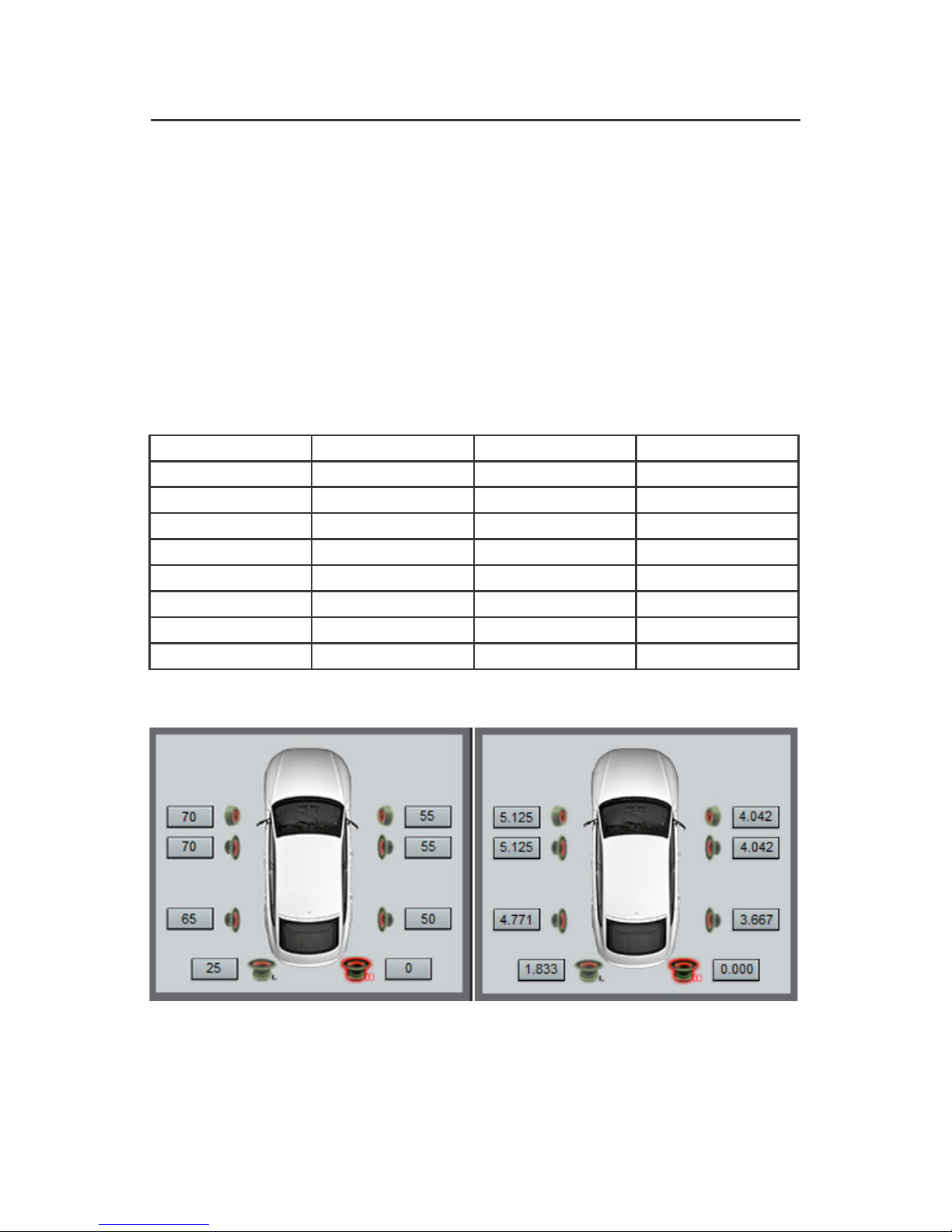
TIME ALIGNMENT INSTRUCTIONS
1. Measure and record the distances from the listening position in the vehicle to each
speaker. The speaker distance that is the farthest away from the listening position will be
the 0 delay reference, because no delay will be needed for this speaker.
2. Subtract each speaker to listening position distance from the 0 delay reference to
determine the amount of time delay to input into the DSI-2 software.
Delay Calculation Formula:
0 Delay Reference - Speaker Distance = Delay Duration
Example: Measured from the front left listening position, the farthest speaker is 100 inches
from the listening position. Notice that the speakers closest to the listening position will
have more delay and the speakers that are farther away will have less delay. This enables
the sound to arrive to the listening position at the same time.
DD AUDIO / DSI-2 / 9
Front Left Position 0 Delay Reference Speaker Distance Delay Duration
CH1 100IN 30IN 70IN
CH2 100IN 45IN 55IN
CH3 100IN 30IN 70IN
CH4 100IN 45IN 55IN
CH5 100IN 35IN 65IN
CH6 100IN 50IN 50IN
CH7 100IN 75IN 25IN
CH8 100IN 100 IN0IN
Inches: Milliseconds:
Table des matières