DayTronic 3000 series Manuel utilisateur

MODEL
3170
STRAIN GAGE CONDITIONER
SB.5.1
INSTRUCTION MANUAL
3000
Instrument Series

Copyright © 1996, Daytronic Corporation. All rights reserved.
No part of this document may be reprinted, reproduced, or used in any form or by
any electronic, mechanical, or other means, including photocopying and recording,
or in any information storage and retrieval system, without permission in writing
from Daytronic Corporation. All specifications are subject to change without notice.

Correction
to Model 3170 Instruction Manual, v. SB.5.1
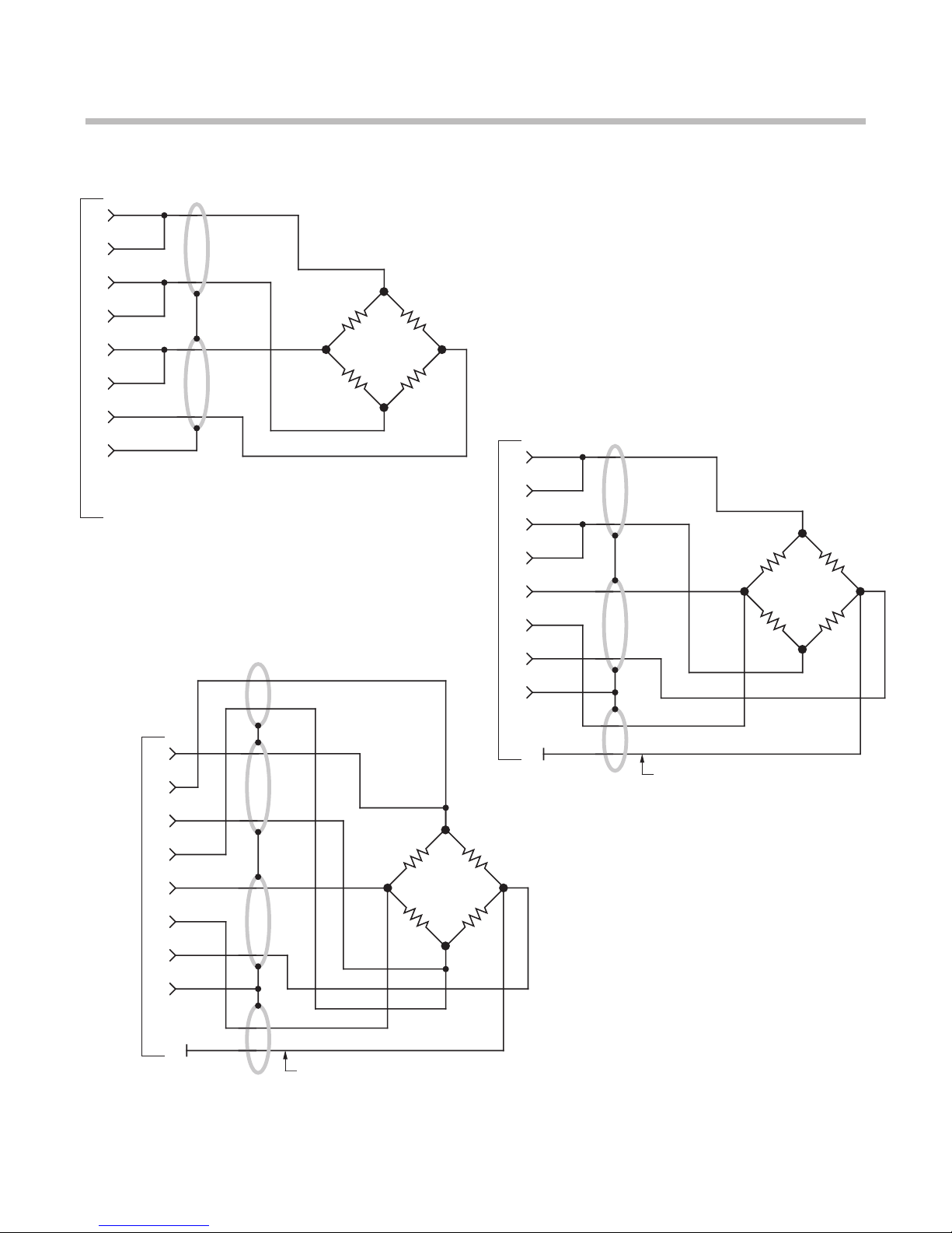
The I/O Wiring Data in Fig. 4 of this manual does not give the correct shield pairing of
cable wires, which is shown in the revised diagrams below and on the following page:
1
A
2
B
3
4
C
9
A
D
B
C
+EXC
–EXC
+SENSE
–SENSE
+SIG
–SIG
CAL SENSE
.
.
.
A
Extra Wire, paired
with CAL SENSE,
unconnected at
Connector A
SHIELD
Bendix PT02E-10-6S
Burndy BT06AC-10-6S
Daytronic 400 Series
Transducer Connections
1
A
2
B
3
4
C
9
D
A
B
C
+EXC
–EXC
+SENSE
–SENSE
+SIG
–SIG
CAL SENSE
.
.
.
A
Extra Wire, paired
with CAL SENSE,
unconnected at
Connector A
SHIELD
Amphenol 97-3106A-
14S-6S, AN3057-6
Daytronic 500 Series
Transducer Connections
(cont’d)
Correction
to Model 3170 Instruction Manual, v. SB.5.1 (cont’d)
+SENSE
–EXC
–SENSE
+SIG –SIG
CAL
SENSE
1
A
2
B
3
C
4
9
.
.
.
A
SHIELD
+EXC
Daytronic 3X70 Instrument to Generalized Strain Gage Transducer
4-Wire Configuration for Cables
Shorter Than 20 Feet
+SENSE
–EXC
–SENSE
+SIG –SIG
CAL
SENSE
1
A
2
B
3
C
4
9
.
.
.
A
SHIELD
Extra Wire, paired with CAL SENSE,
unconnected at Connector A
+EXC
6-Wire Configuration for Cables
Shorter Than 20 Feet
+SENSE
–EXC
+SIG –SIG
CAL
SENSE
1
A
2
B
3
C
4
9
.
.
.
A
SHIELD
Extra Wire, paired with CAL SENSE,
unconnected at Connector A
–SENSE
+EXC
8-Wire Configuration for Cables
Longer Than 20 Feet

MODEL
3170
STRAIN GAGE CONDITIONER
INSTRUCTION MANUAL
Model 3170 Instruction Manual, v. SB.5.1
Pub. No. 3170M.5.1, Issued 03/01
Part No. 91132
Daytronic Corporation
Dayton, OH • Tel (800) 668-4745
www.daytronic.com

Daytronic Corporation
TABLE OF CONTENTS
Section Page
1
Description ................................................. 1
2
Installation and Cabling ......................................
3
3
Calibration .................................................. 8
4
Block Diagram Description ................................... 12
5
Verification of Normal Operation ..............................
14
LIST OF ILLUSTRATIONS
Figure
Page
1
Model 3170 Strain Gage Conditioner...........................
1
2
Instrument Mounting Dimensions ............................. 4
3
Instrument Panel Mounting .................................. 5
4
I/O Wiring Data ............................................
.
9
5
Front-Panel Description ...................................... 11
6
Block Diagram .............................................. 15
7
Star-Bridge Construction ..................................... 17
LIST OF TABLES
Table
Page
PLEASE NOTE: Sections 6 and 7, Figures 8 and 9, and Table 2 have been
removed from this manual.
If you need information regarding specific 3170 components and circuitry,
please contact the Daytronic Service Department at (937) 293-2566.
1Specifications ............................................... 2

Daytronic Corporation
INSTRUCTION MANUAL
MODEL 3170 STRAIN GAGE CONDITIONER
1. DESCRIPTION
The Model 3170 conditioner-amplifier module for use with resistance strain
gage transducers. It supplies a regulated dc excitation voltage to the transducer
bridge, provides the necessary balancing and calibration controls, and amplifies the
resulting signal to a standard Five-Volt Data Signal Level which is the output analog
signal level of 3000 Series Modules. The
3170
has three separate analog outputs,
each having a different bandpass: (1) dc to 2
kHz,
(2) dc to 200 Hz, and (3) dc to 2
Hz. Active low-pass filters are used to achieve the 200 Hz and 2 Hz cutoff
frequen-
cies.
The filtered outputs provide for averaging or smoothing signals containing
noise or other unwanted dynamic components which are periodic in nature. Filter-
ing removes these dynamic components so that stable digital indication and precise,
jitter-free control action can be obtained. The Model 3170 is shown in Figure 1 and
the specifications are given in Table 1.
Figure 1. Model 3170 Strain Gage Conditioner
1

Model 3170
Table
1.
Specifications
Transducers: 4-arm bridges, 90
to
2000 ohms, nominally 1
to
8
mv/v,
full
scale (120 ohms or less requires use of 5-volt excitation).
Cables:
4-,
5-,
or 7-wire, depending on application; 1000
feet
maximum length.
Bridge Excitation: Regulated 5 volts or 10 volts dc, selected
with
I/O
connector wiring. Transducers
with
sensitivity from 4 to 8
mv/v
full
scale must use
5-volt
excitation.
Balance Adjustments:
10-turn
coarse and fine; will balance 1.5
mv/v
initial unbalance.
Span Adjustments:
10-turn
coarse and fine; 1to 8
mv/v,
full scale.
Analog Outputs: Three analog outputs available; 0 to ±5 volts with
50% overange,
5
milliamperes maximum.
Bandpass
is dc
to
2 kHz, dc
to 200 Hz, or dc to 2 Hz, depending on
output
used. Active low-pass
filters provide for rolloff of 60
dB
per decade above cutoff frequency.
Full-scale slew
time
is 1.4/f seconds, where f is
the
cutoff frequency.
Common Mode Rejection: Greater
than
80
dB.
Output Ripple and Noise: 0.15% of full scale (rms) maximum for
2-kHz and 100-Hz outputs; 0.02% of full scale (rms) on 2-Hz output.
Accuracy: 0.05% of full scale.
Dimensions: 1.7 x 4.41 x 8.5 (HWD inches).
Operating Temperature Range: 0 to + 130 degrees F.
Power Requirements: 105 to 135 volts ac, 50 to 400 Hz at 5 watts
maximum.
2

Daytronic Corporation
Remote sensing techniques are used to regulate the excitation voltage at the
transducer. Either a 10-volt or a
5-volt
excitation voltage can be selected by
appropriate wiring at the module
I/O
connector. The excitation voltage is protected
against overloads and accidental short circuits.
The 3170 uses a CMOS chopper-stabilized differential signal amplifier which
has over
100-megohms
input impedance per input line. This circuit guarantees
negligible drift with temperature variations or component aging.
Calibration of the 3
170
is accomplished by the conventional shunt technique,
using an internally installed calibration resistor. A front-panel CAL button or
Remote
Cal
terminals on the module I/O connector can be used to initiate the
calibration procedure.
The 3
170
Strain Gage Conditioner is also available in two additional forms. The
Model 3270 includes the addition of a digital indicator to view the analog output of
the conditioner. The Model 3370 includes a Limit section (in addition to a digital
indicator) which provides high, low, and ok indications and outputs. The digital
indicator and limit options are standard to all 3000 Modules and are covered in
separate instruction manuals.
2.
INSTALLATION AND CABLING
The following paragraphs provide the instructions for module installation and
cabling.
Module Mounting. The 3000 Series Modules can be operated as bench-top
instruments or they can be rack- or panel-mounted. Clearance dimensions for a
bench-mounted instrument are given in Figure 2. Panel cut-out dimensions for
panel mounting are also shown in Figure 2. Up to four 3000 Series instruments can
be mounted in a
19-inch
rack using the
1.75
-inch high Model 3004 Rack Adaptor.
Rack-mounting dimensions are also given in Figure 2. To panel mount an instru-
ment, proceed as follows. Refer to Figure 3.
Important: The unit is shipped with two spacer washers on the securing screws of the
rear-panel I/O Connector. When panel-mounting the unit, you MUST REMOVE
THESE WASHERS, so that the printed-circuit board may move forward about 1/8"
during Step (f).
(a)
Remove the front panel by removing the two 2-56 x
3/8
flat-head screws.
3

4
Model 3170
Figure 2. Instrument Mounting Dimensions
C. Panel Mounting
B. Rack Mounting
A. Bench Mounting
Autres manuels pour 3000 series
2
Ce manuel convient aux modèles suivants
1
Table des matières
Autres manuels DayTronic Amplificateur


