DAVIS Daytime Fan-Aspirated Radiation Shield Kit Manuel utilisateur
1
Daytime Fan-Aspirated Radiation
Shield Kit Installation Manual
For Vantage Pro2™& Vantage Pro2 Plus™Stations
Introduction
The instructions describe how to upgrade a non-aspirated Vantage Pro2™
radiation shield to a Daytime Fan-Aspirated Radiation Shield.
The upgrade kit can be installed on any Vantage Pro2™or Vantage Pro2
Plus™Integrated Sensor Suite (ISS) equipped with a non-aspirated radiation
shield.
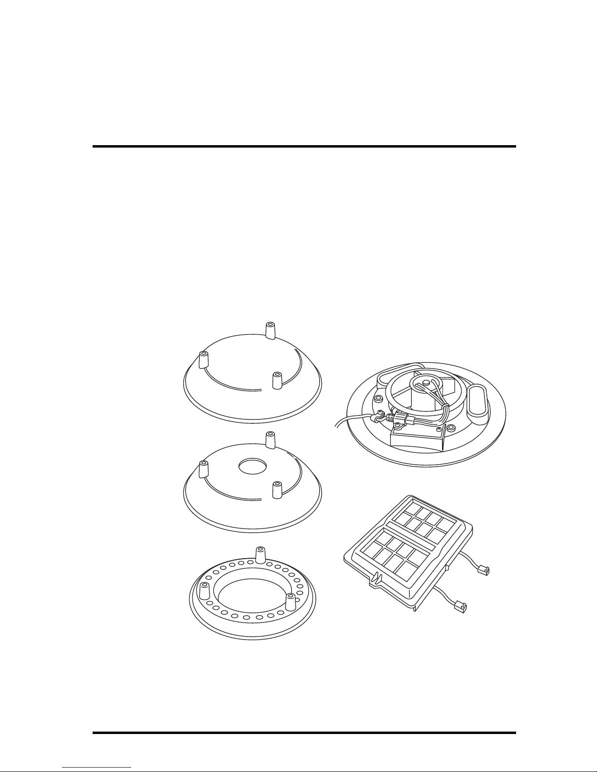
Components
The upgrade kit includes the following components:
Closed Cap Plate
Open Cap Plate
Open Plate
SIM Cover
Fan Plate
Daytime Fan Kit Components

Installing the Daytime Fan Kit
2
The kit also includes the following hardware:
Tools Needed
You may need some or all of the following tools to complete the upgrade:
• A medium Phillips-Head screwdriver
• A medium slot-tip screwdriver
• Other tools as required to remove and re-mount the ISS
• Cabled ISS Only: Wire cutters
Installing the Daytime Fan Kit
Installation Overview
These are the steps to install the Daytime Fan components:
1. For Consoles Only — Put the console into Setup Mode.
2. Take the ISS down from its installed position.
3. Disassemble the standard radiation shield.
4. Check Temperature/Humidity sensor orientation.
5. Assemble the lower section of the fan-aspirated shield.
6. Install the fan unit.
7. Assemble the upper section of the fan-aspirated shield.
8. Re-Install the ISS.
9. Take the console out of Setup Mode.
For Consoles Only— Put Console in Setup Mode
If you have a console, you need to put it in Setup Mode. This prevents the
reception of erroneous data while you are removing the ISS.
If you have an Envoy and are concerned with erroneous data, you may edit the
data via the WeatherLink software. See the WeatherLink Online Help for more
information.
#8-32 x 3-1/4" Screws
(3)
#8-32 x 1/2" Screws
(3) Threaded Spacers
(3)
#8 Split-Lock Washers (6)
#8 Flat Washers (6)
12" Cable Ties (2)
1" Spacers
(2)
#4 Screws
(2)
Daytime Fan Kit Hardware

Installing the Daytime Fan Kit
3
To put your console in Setup Mode:
At your Vantage Pro2 console, press and hold DONE and then press the
down arrow (-) to put the console in Setup Mode. This prevents the
reception of erroneous data while you are removing the ISS.
Note: If the console acquires erroneous data during the upgrade, see Take the Console Out
of Setup Mode on page 15 for instructions on clearing data. Additional information on
clearing console data can be found in the Vantage Pro2 Console Manual.
Take Down the ISS
Please work on your Vantage Pro2 ISS in a safe place. If you are installing the
Daytime Fan Kit on an ISS that has already been placed into service, you will
need to take down the ISS from its sited location and move it to a convenient
and safe place to perform the installation.
To disassemble the ISS:
1. Locate the Sensor Interface
Module (SIM) housing cover
on the side of ISS and open it.
2. Disconnect the Solar Panel
wire on the SIM cover from
the SIM board by pulling the
Solar Panel connector.
3. Pull the foam insert out of the
cable access port in between
the cables and set the foam
insert aside.
4. Disconnect the anemometer
cable from the sensor
connector labeled WIND and,
if you are using a cabled
model, disconnect the console
cable from the SIM and slide
the cables out of the cable
access port.
5. You can now remove the ISS from its mounted position. Move it to a safe
place to install the kit components.
Disassemble the Standard Radiation Shield
Note: We recommend using a workbench or table to perform the following procedures.
1. Open and remove the SIM cover if you have not done so already.
2. Disconnect the Temperature/Humidity cable from the SIM and slide the
cable out of the cable access port.
Lift off cover,
unplug solar power
connector
Detaching the SIM Cover

Installing the Daytime Fan Kit
4
3. Remove the rain collector cone from the ISS
base by rotating the cone counter-clockwise.
When the cone’s latches line up with openings
in the base, you can lift the cone off. The cone
fits in the base tightly and may require extra
pressure to remove the first few times.
Steady the ISS base between your knees when
removing the cone
4. Remove the three 8-32 x 4'' screws
holding the radiation shield plates
together.
5. Save these three screws and
washers, and separate out the
radiation plating.
Depending on the placement of the
Temperature/Humidity sensor, you
may need to reorient the sensor
before assembling the lower section
of the radiation plating. See Check
Temperature/Humidity Sensor
Orientation on page 5 for more
information.
Twist to Open
Remove the Rain
Collector Cone
4"
Screw
Plates
Rain Collector Base
Temperature/
Humidity
Sensor
Lock
Washer
Flat
Washer
Standard Radiation Shield Assembly Diagram
Note: Placement of the Temperature/Humidity Sensor
may vary.

Installing the Daytime Fan Kit
5
Check Temperature/Humidity Sensor Orientation
The orientation and placement of the Temperature/Humidity sensor should be
checked, and in many cases, should be reoriented. There are three ways the
sensor could be mounted in an ISS:
• On the second to bottom-most plate of radiation plating stack with the
Temperature/Humidity sensor facing up.
• Underneath the top plate of the radiation plating stack, on the insulating
disk with the Temperature/Humidity sensor facing down.
• On the second to bottom-most
plate of the radiation plating stack
with the Temperature/Humidity
sensor mounted on spacers,
facing down.
If the Temperature/Humidity
sensor is mounted on the second
to bottom-most plate with the
sensor facing down, it is in the
correct orientation and does not
need to be repositioned in the
stack.
If the Temperature/Humidity
Sensor is placed in one of the
other two positions, it should be removed from its current position and
remounted in the correct position shown above.
Reinstall the Temperature/Humidity Sensor — For Sensors Facing Up
1. Locate the
Temperature/Humidity sensor
on the second to bottom plate
in the radiation shield plating
stack.
2. Remove the three screws, flat
washer, and cable clamp
securing the
Temperature/Humidity sensor
to the radiation plating. Save
the small screw, flat washer,
and cable clamp for use later.
Temperature/Humidity Sensor correctly
mounted on spacers
Cable Clamp
Temperature/Humidity
Sensor
Removing Temperature/Humidity Sensor with
sensor mounted up
Installing the Daytime Fan Kit
6
3. Reinstall the sensor face down on the
radiation plate, using the two 1'
spacers and #4 screws included with
the kit.
4. Put the cable clamp back on the
cable and use the screw and flat
washer to resecure the cable onto the
radiation plate.
5. Replace the radiation plate back in
its correct place in the radiation
shield plating stack.
Reinstall the Temperature/Humidity Sensor — For Sensors on the
Insulating Disk
1. Locate the plate at the top of the
radiation shield plating and find the
insulating disk with the
Temperature/Humidity sensor on
the underside of the radiation
shield.
2. Remove the three screws, flat
washer, and cable clamp securing
the Temperature/Humidity sensor to
the insulating disk. Save the small
screw, flat washer, and cable clamp
for use later.
3. Remove the two screws holding the
insulating disk attached on the
underside and discard the disk.
4. Reinstall the sensor face down on
the second to bottom-most radiation
plate, using the two 1' spacers and
#4 screws included with the kit. See
figure Reinstalling
Temperature/Humidity Sensor with
Sensor Mounted Down for more
information on mounting the
sensor.
Temperature/
Humidity
Sensor
#4 Screws (2)
Spacers (2)
Cable Clamp
Reinstalling Temperature/Humidity Sensor with
Sensor Mounted Down
Insulating
Disk
Cable
Clamp
Temperature/
Humidity
Sensor
Removing Temperature/Humidity Sensor with
sensor mounted on Insulating Disk

Installing the Daytime Fan Kit
7
5. Put the cable clamp back on the cable and use the screw and flat washer to
resecure the cable onto the radiation plate.
6. Replace the radiation plate back in its correct place in the radiation shield
plating stack.
Assemble the Lower Section
Once the existing radiation shield has been disassembled and the
Temperature/Humidity sensor has been mounted correctly in the radiation
plating stack, the existing disks have to be re-organized and assembled with
the fan-aspirated kit. To reassemble the radiation shield with the new
fan-aspirated shielding:
1. Locate the plate at the top
of the radiation shield
plating and find the
insulating disk on the
underside of the radiation
shield.
2. Remove the two screws
holding insulating disk
attached on the underside
and discard it. Save the top
plate for use in Step 3.
3. Start building the lower
section of the new radiation
shield, starting with the
original bottom plate on
bottom and the
disassembled top plate above that.
4. Place the plate containing the Temperature/Humidity sensor and the two
open plates on top of the two bottom plates.
Note: When stacking plates, make sure the screw bosses (holes) line up with each other.
5. Place the third open plate (supplied with the fan-aspirated kit) on the stack.
Remove the Insulating Disk
Top Plate
Insulating Disk

Installing the Daytime Fan Kit
8
6. Run the Temperature/Humidity cable through the top of the three open
plates.
7. Set aside the re-assembled radiation shielding and find the fan plate motor
assembly.
Fan Plate
Plates
Flat Washer
Lock Washer
4" Screws
Temperature/
Humidity
Cable
New Open Plate
Reassemble the Radiation Shield Plates with the Fan
Plate

Installing the Daytime Fan Kit
9
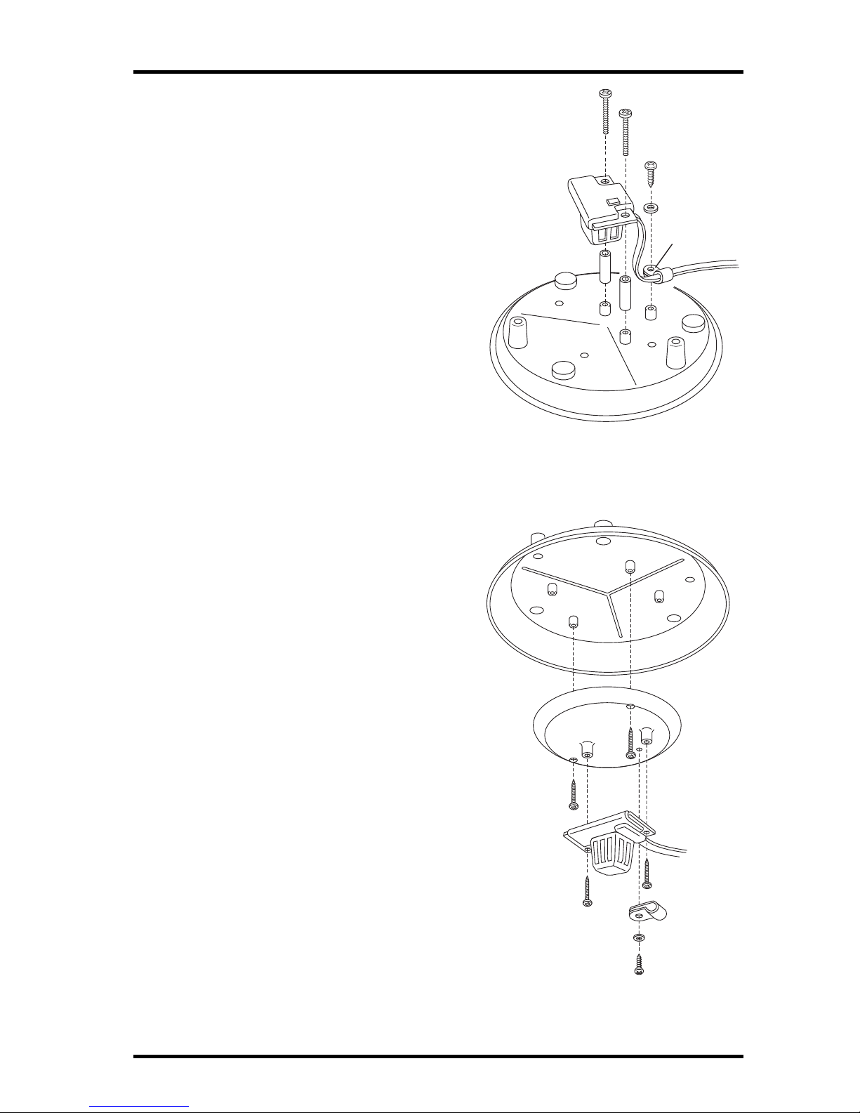
8. Attach the three threaded spacers to the fan plate using the three #8-32 x
1/2'' screws and the three #8 washers and #8 lock washers included with
the kit.
Install Threaded Spacers
9. Detach the fan motor cable from the power cable assembly on the fan plate
and set the fan motor aside.
Detach Fan Motor Cable
10. Lower the Fan Plate onto the radiation shielding stack.
Fan Plate
Threaded
Spacer
(3)
#8 Flat Washer
#8 Split-Lock Washer
#8-32 x 1/2" Screw
Fan Plate
Fan Plug
Power Cable
Assembly
Fan Motor
Assembly

Installing the Daytime Fan Kit
10
11. Bring the Temperature/Humidity cable over the top of the fan plate so that
no slack in the cable exists between the sensor and the fan plate and press it
firmly into the cable channel on the fan plate.
Fan Plate
Channel
Temperature/Humidity
Cable
Lift Fan Motor up
and set aside
Connecting the Radiation Shield and Fan Unit
Ce manuel convient aux modèles suivants
1
Table des matières


