Datacolor 245 Manuel utilisateur

Datacolor
Datacolor 245™
User’s Guide

Datacolor 245™ User’s Guide (January, 2005) Part No. 4230-0393M
All efforts have been made to ensure the accuracy of the information presented in this
format. However, should any errors be detected, Datacolor appreciates your efforts to
notify us of these oversights.
Changes are periodically made to this information and are incorporated into forthcoming
versions. Datacolor reserves the right to make improvements and/or changes in the
product(s) and/or program(s) described in this material at any time.
Copyright © 2005 Datacolor. ALL RIGHTS RESERVED. This material may not be
reproduced or duplicated, in whole or in part, without the express written permission of
Datacolor.
Microsoft®, MS-DOS®, and Microsoft Windows® are registered trademarks of Microsoft
Corporation. All other registered trademarks are the property of their respective owners.

Datacolor 245™ User's Guide Contents •i
Contents
Datacolor 245™ .................................................................................................... 1
About the Datacolor 245™ .............................................................................. 1
Electrical and Environmental Requirements............................................. 2
Safety Warnings........................................................................................ 2
Feature Summary ..................................................................................... 2
Accessories ..................................................................................................... 3
Calibration Tiles ........................................................................................ 3
Aperture Plates ......................................................................................... 3
Cable Installation ................................................................................................. 5
Instrument Cables ........................................................................................... 5
Power Cable.............................................................................................. 5
Communications Cable............................................................................. 6
USB Driver Installation .................................................................................... 7
Installing the Driver ................................................................................... 7
Viewing/Changing System Port Assignment .......................................... 12
Changing the COM Port Assignment in Datacolor Programs................. 16
Installing Calibration Data ....................................................................... 16
Controls and Indicators..................................................................................... 17
Status Panel .................................................................................................. 17
Powering Up .................................................................................................. 18
Instrument Calibration ................................................................................... 18
Sample Presentation and Measurement.......................................................... 21
About Sample Presentation........................................................................... 21
Sample Viewing Port............................................................................... 22
Maintenance ....................................................................................................... 25
About Instrument Maintenance ..................................................................... 25
Tile Handling and Cleaning ........................................................................... 25
Handling Tiles ......................................................................................... 25
Cleaning Tiles ......................................................................................... 25
Storage.................................................................................................... 26
Cleaning the Black Trap.......................................................................... 26
Appendix............................................................................................................. 27
Datacolor 245™ Optical Block Diagram........................................................ 27
Instrument Specifications .............................................................................. 28
Miscellaneous Technical Information ............................................................ 29
RS-232C Connector Pin Assignments.................................................... 29
Safety Warnings ............................................................................................ 29
Light Source ............................................................................................ 29
Side Vents............................................................................................... 29
Compliance Statements ................................................................................ 30
FCC Compliance Statement ................................................................... 30
Canadian Compliance Statement ........................................................... 30
Index.................................................................................................................... 31

Datacolor 245™ User's Guide About the Datacolor 245™ •1
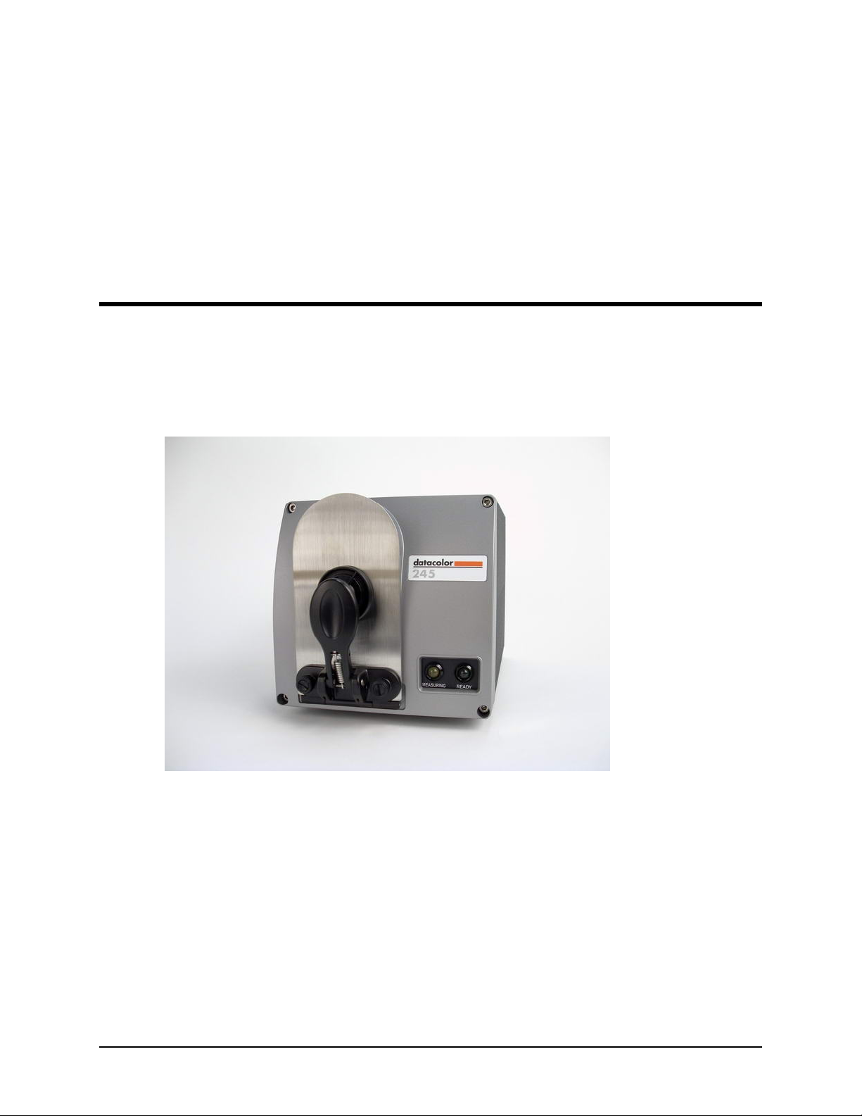
Datacolor 245™
About the Datacolor 245™
The Datacolor 245 provides a new, solid-state approach to 45º/0º measurement geometry.
It employs a unique, dual-beam optical design, uses a pulsed xenon lamp and has a sealed
optical path for improved repeatability and long-term stability. 45º/0º instruments are used
for quality control applications when both color and appearance features are being
evaluated.
The Datacolor 245 includes the following standard features:
•Dual-beam measurement using pulsed xenon light source
•Datacolor proprietary high-end sensor
•Conformance to ASTM E1164 Standard Practice for Obtaining
Spectrophotometric Data for Object-Color Evaluation
•Drawer for accessories
•Datacolor world wide support
2 •About the Datacolor 245™ Datacolor 245™ User's Guide
Electrical and Environmental Requirements
Power 85 to 264 VAC
47 to 63 Hz
80 VA peak
35 VA typical
Absolute Operating Environment 5º to 40º C
65%-85% RH, non-condensing
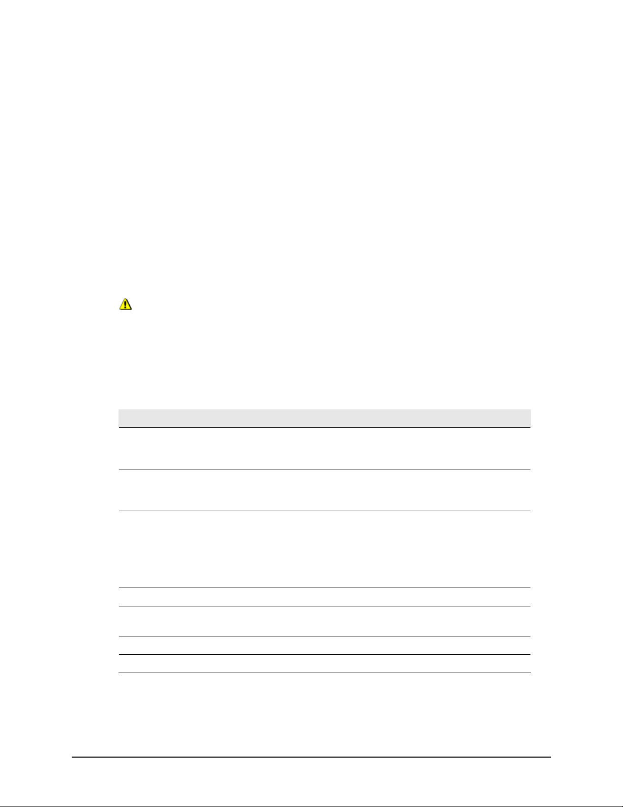
Safety Warnings
Light Source
Do not stare directly into the open port located in the front door panel when the
measurement is in progress. Staring directly into the light source can result in eye
discomfort similar to that of staring at a camera flash.
Side Vents
Vents are included along each side of the instrument to facilitate air circulation. HIGH
VOLTAGE COMPONENTS WITHIN. DO NOT INSERT ANY OBJECTS INTO THESE
OPENINGS!
Feature Summary
The Dataflash is one of a family of Datacolor instruments that employs state-of-the-art
features including the spectrometer, light source, and optics. Below is a summary of those
features:
FEATURE DESCRIPTION PURPOSE/BENEFIT
Instrument Type Dual-beam
spectrophotometer with
xenon flash lamp
Industry standard.
Measurement
Geometry
45º illumination
0º viewing
Results provide good
agreement with visual
evaluations of sample color.
SP2000 Spectral
Analyzer
Proprietary dual-channel
holographic grating. 256-
photodiode linear arrays
used for both the
reference and sample
channels.
Dual channel design provides
continuous monitoring of sample
illumination and compensates
for changes. 256-photodiode
array enhances the precision of
the measurement.
Light source Pulsed xenon flash lamp Does not require warm up
Effective
Bandwidth
10nm Greater precision enhances the
measurement accuracy.
Wavelength Range 400nm to 700nm
Reporting Interval 10nm
Datacolor 245™ User's Guide Accessories •3
Accessories
All models come with the following standard accessories:
•Six foot power cable
•Serial cable with connectors on either end
•USB cable
•Black Trap
•White Tile
•Green Tile
In addition, an optional accessory drawer is available with the unit.
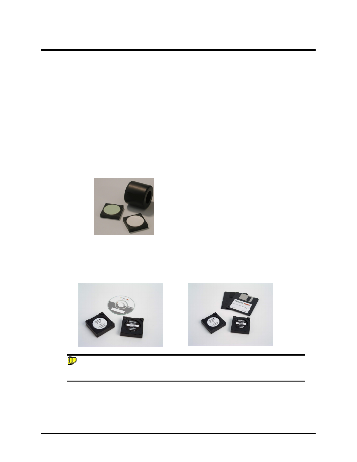
Calibration Tiles
A black trap, white tile and green tile are provided with Datacolor instruments.
•The black trap and white tile are used each time the instrument is calibrated.
•The green tile is used to perform an optional diagnostic test.
Calibration Data
The calibration procedure uses white data that must be installed on the system. It is data
unique for the white calibration tile, and is provided on either a diskette or a CD. It is
included with the instrument accessories:
NOTE
The serial number on the back of the white calibration standard should match the serial
number on the instrument.
Aperture Plates
The Datacolor 245 is a single aperture instrument. Refer to Appendix, Features by Model
for the aperture specification.

4 •Accessories Datacolor 245™ User's Guide
This page intentionally left blank.
Datacolor 245™ User's Guide Cable Installation •5
Cable Installation
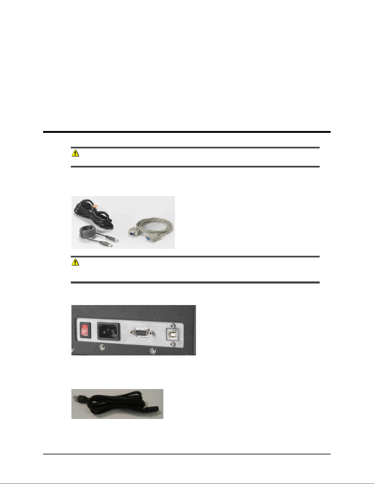
Instrument Cables
WARNING
BE SURE TO TURN OFF THE POWER BEFORE WORKING WITH ANY CABLES.
The Datacolor 245 requires the use of two cables, a power cable and either a serial cable
or a USB cable, to connect the instrument to the computer.
WARNING
Read "Electrical and Environmental Requirements section before connecting your
instrument.
The connections for these cables are found on the back of the instrument.
Power Cable
A six-foot power cable is provided with the instrument.
Power is supplied to the back of the unit via a 3-prong male connector.
6 •Cable Installation Datacolor 245™ User's Guide
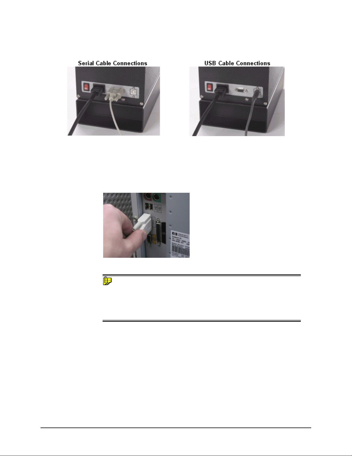
Communications Cable
The instrument is connected to a computer through either a serial port or USB port:
1. Plug the female end of the power cord into the power receptacle on the rear
panel of the instrument. Insert the plug into a standard AC outlet.
2. Connect the male connector on the instrument cable to the appropriate female
connector on the rear panel of the instrument.
3. Connect the female connector on the instrument cable to a communications port
on the back of the computer.
4. Tighten each connection securely to ensure proper signal.
NOTE
If there is more than one serial port on the computer, make a note of the port
being used. You may need to enter this information into the program.
See USB Driver Installation in this guide for detailed instructions regarding
the software installation. See the Appendix for a description of the RS-232C
connector pin assignments.
Ce manuel convient aux modèles suivants
1
Table des matières
Autres manuels Datacolor Équipement industriel


