CYP CPRO-A1 Manuel utilisateur

CPRO-A1
Sound Bar
Operation Manual
CPRO-A1

Safety Precautions
Please read all instructions before attempting to unpack or install or
operate this equipment, and before connecting the power supply.
Please keep the following in mind as you unpack and install this
equipment:
Always follow basic safety precautions to reduce the risk of
fire, electrical shock and injury to persons.
To prevent fire or shock hazard, do not expose the unit to rain,
moisture or install this product near water.
Never spill liquid of any kind on or into this product.
Never push an object of any kind into this product through
module openings or empty slots, as you may damage parts.
Do not attach the power supply cabling to building surfaces.
Do not allow anything to rest on the power cabling or allow it to
be abused by persons walking on it.
To protect the equipment from overheating, do not block the
slots and openings in the module housing that provide
ventilation.
Revision History
Version No Date Summary of Change
RDV0 20110630 Preliminary Release

Table of Contents
1
1
1
1
2
2
2
3
4
5
5
7
8
8
9
13
14
1. Introduction ……………………..……………………..…........….…….
2. Applications …………………..………………….……...................…..
3. Package Contents ………………………...........……….................…
4. System Requirements ……………..……….........………............…….
5. Features …………………………………………......……........…...……
6. Audio Input Specications …………….…...……..........………....….
7. Analog Audio Output Specication …………….…...…...……....….
8. Amplier Performance …………….…........................…...……....….
9. Specication …………….…........................................…...……....….
10. Operation Controls and Functions ……………...……..............……
10.1 Front Panel ............................................................................
10.2 Rear Panel .………………………….....…..…….......…...….…
11. Remote Control .......................…......……………..........…..…....…...
11.1 Dip Switch ..............................................................................
12. OSD Chart .........................................................................................
13. Connection and Installation ….………………….........…..…..…......
14. Acronyms …......................................................................................

1. Introduction
As we advance we are able to create some amazing pieces of technology,
on ofthose creations is the Sound Bar. With its sleek, modern design that
includes built inspeakers, this Sound bar is superior to most thanks to its
umerous new features and compact design. HDMI TM compliant and
supporting 7.1 channel surround soundthe Sound Bar is a single piece speaker
system designed so you can enjoy highquality surround sound without going
through the hassle of a multi-speaker setup. The Sound Bar makes your
entertainment world complete.
2. Applications
Home Theater
Showroom
Concert Room
Dancing Room
Display Room
3. Package Contents
Sound Bar x 1
Remote Control x 1
Alkaline AAA battery x 2
Operation Manual x 1
24V / 6.75A Power adaptor x 1
Power Cord x 1
4. System Requirements
Input source equipments such as DVD/Blue-Ray player, Set-Top-Box, VCR,
and or PS3 amplifier with up to 7.1 Channels connection cables and output
display HD TV/monitor.
1

5. Features
HD Sound Theater Technology
HDCP and CEC compliant
HDMI v1.4 with:
Audio Return Channel
Fast switching on all HDMI input ports in less than 1 second
EIncludes a built-in HDMI EDID simulator and HDCP keset which allows
independent audio source selection.
HDMI output with xvYCC to RGB color space design
Support HDMI CEC bypass and HDCP repeater
Easy to install and operate
User friendly OSD menu
Large, easy to read LCD display
Audio supports:
Different audio sound mode (Jazz/music/Speech/Concert/Movie)
Dedicated, flexible and full audio input and output
Flexible Subwoofer setting (internal or external)
Audio Channel Level +/- 10dB
7x Passive speaker 4ohm~8ohm
PCM 2.0, 5.0 & 7.1
Sampling rate up to 192kHz
HDMI compatible audio interface
6. Audio Input Specications
1. Analog Input
(1). Max. Input Level: 2Vrms
(2). Input Impedance: 47k ohm
2. Coaxial Digital Input
(1). Max. Input Level: 0dBFS
(2) Input Impedance: 75ohm
3. HDMI Ditigal Input
(1). Max. Input Level:0dBFS
(2). HDMI Differential Impedance: 100+/-10%ohm(TMDS)
7. Analog Audio Output Specication
1. Sub Woofer Output
(1). Max Output Level: 1.7Vrms
(2). Output Imedance: 620ohms
(3). SNR>85dB@0dbFs
(4). Sub Woofer -3dB, Frequency: 100Hz
2

8. Amplier Performance
(1). Analog Input sensitivity: 200mVrms
(2). Digital Input sensitivity: -20dBFS
(3). Frequency Response<+-1dB@20Hz~20KHz
(4). THD+N<0.05%@1W 20Hz~20KHz
(5). SNR >120dB a-weighted
(6). class D amplify efficient > 80%
(7). Amplifier OUTPUT
Front:
50W+50W @4Ω<1%THD+N@1KHz
25W+25W @8Ω<1%THD+N@1KHz
Center
50W+50W @4Ω<1%THD+N@1KHz
25W+25W @8Ω<1%THD+N@1KHz
Surround
50W+50W @4Ω<1%THD+N@1KHz
25W+25W @8Ω<1%THD+N@1KHz
Surround Back
50W+50W @4Ω<1%THD+N@1KHz
25W+25W @8Ω<1%THD+N@1KHz
Amplier Performance
THD+N Ratio Vs Level (4OHM) THD+N Ratio Vs Level (8OHM)
Level Vs Frequency Response (1W) THD+N Vs Frequency Response(1W)
3

9. Specications
Input ports 3 x HDMI, 1 x Coaxial, 1x Optical,
1 x Analog 7.1 or 4x Analog Stereo
Output ports 1 x HDMI, 1 x Subwoofer,
VIDEO Support Resolution 480i~1080p 50/60/24, VGA ~WUXGA
HDMI Cable IN/OUT 15M/15M
Audio Analog IN/OUT Impedance 47kohm/620 ohm
Audio Analog INPUT Max. 2Vrms
Audio Sensitivity 200mV
Audio TYPE LPCM2.0, 5.1 & 7.1
Audio Sampling 32k~192kHz
Power Supply 24V/6.75A DC (US/EU standards,
CE/FCC/UL certified)
Dimensions (mm) 280 (W) x 162(D) x 49 (H)
Chassis Material Metal
Silkscreen Color Silver
Operating Temperature 0˚C ~ 40˚C / 32˚F ~ 104˚F
Storage Temperature -20˚C ~ 60˚C / -4˚F ~ 140˚F
Power Consumption 150W
Relative Humidity 20~90% RH(non-condensing)
4

10. Operation Controls and Functions
10.1 Front Panel
① ② ④ ⑥⑦⑧③ ⑤
Video Mute
Audio Info
Power
Menu /
Volume
①IR window: This is the IR receiver window which receive IR signal from the
remote control included in the device package.
②LED monitor: This monitor will display the setting status.
③Video: Press this button to select HDMI input from 1~4
④Audio: Press this button to select audio input from analog RCA or digital
coaxial input.
⑤Mute: Press this button to mute the audio sound.
⑥Power: Press this button to turn on or set the device to standby mode.
⑦Info: Press this button to bring up the information screen and press it again
to exit it.
⑧Menu/Volume wheel: Turn this wheel to turn up or down the volme or
when selecting the OSD turn it to right or left to bring in and out the OSD
sele
5

6.2
6.1
6.3 6.5 6.9
6.86.7
6.4 6.6 6.10
6.1 Audio Type: This LED will show output audio format setting from
LPCM 2.0/ 5.1./7.1.
6.2 Sound Mode: This LED will show output sound format setting from
Default/Concert/Speech/Movie/Music or Jazz.
6.3 MUTE: This LED shows the output audio is being muted, when
the LED is off the output audio will output sound again.
6.4 Audio Input: This LED shows the audio input format setting from
Digital HDMI 1~4/Digital Coaxial/analog 7.1CH or Analog Stereo.
6.5 Video Input: This LED shows the video input format setting from HDM
1~4.
6.6 Video Resolution This LED shows the output video resolution
according to the display monitor or TV or the built-in EDID.
6.7 OSD Upper Layer: This LED shows the device’s mode or the upper
level of the OSD selection.
6.8 OSD Lower Layer: This LED shows from the upper level to the lower
level of the OSD selection but the default will always goes back to
the main volume setting.
6.9 Volume: This LED shows the present volume setting.
6.10 Speaker: These LEDs shows the output speaker connection.
6
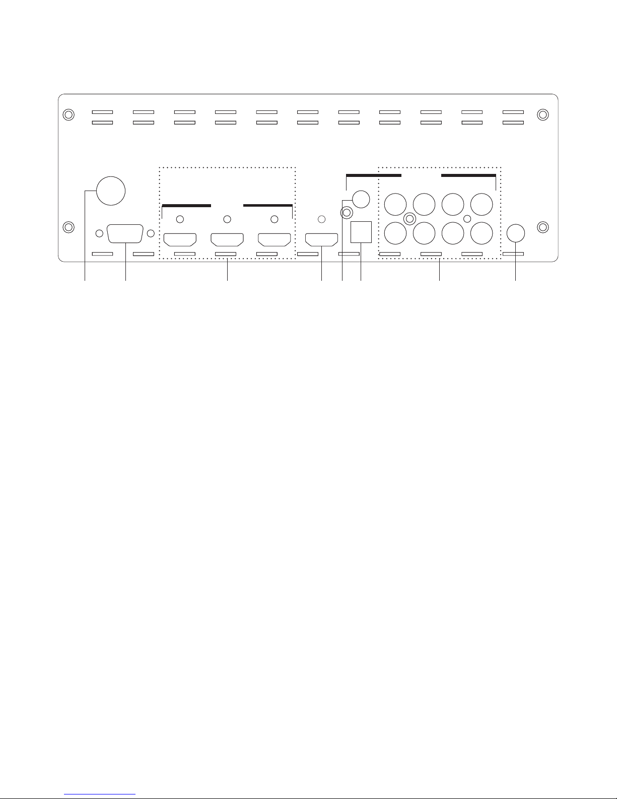
10.2 Rear Panel
③② ④ ⑧⑦⑥① ⑤
123
1234
FRONTSUB.SUR.SUR-BACK
DC 24V
RS 232
HDMI IN HDMI OUT
123
AUDIO IN
SUB OUT
COAXIAL
OPTICAL CENTER
1234
FRONTSUB.SUR.SUR-BACK
L
R
①DC 24V: This slot is to connect with power adaptor and power cord
included in the package and connect it to the AC wall outlet for power
supply.
②RS-232: This slot is to connect with D-sub 9pin cable from PC/NB for RS-232
control and command sending.
③HDMI Input 1~3: These slots are for connecting the input source
equipments such as DVD or Blue-Ray player for both video and audio
signal input with HDMI cables.
④HDMI Out: This slot is to connect with display equipment such as HD TV/
monitor for output video signal display with HDMI cable.
⑤COAX IN: This slot is to connect with input source equipment such as DVD
or Set-Top-Box for audio signal input with coaxial cable.
⑥OPTICAL IN: This slot is to connect with input source equipment such as
DVD or Set-Top-Box for audio signal input with optical cable.
⑦Analog Audio Input: These slots are for connecting the analog audio
signal from input source equipment such as Set-top-Box or VCR with RCA
cables up to 7.1 channels.
⑧SUB Out: This slot is to connect to the subwoofer speaker for external
subwoofer sound display.
7
Table des matières
Manuels Système de haut-parleurs populaires d'autres marques


Sondpex
Sondpex Active Speaker System and Digital Music... Manuel utilisateur

JVC
JVC NX-PN7 Manuel utilisateur

Marshall Amplification
Marshall Amplification AR-DM61-BT Manuel utilisateur

Yamaha
Yamaha NX-A01 - Speaker Sys Manuel utilisateur

SE Audiotechnik
SE Audiotechnik I-LINE Manuel utilisateur

Gemini
Gemini WRX-843 Series Manuel utilisateur