CYP CH-2602RX Manuel utilisateur

CH-2602RX
HDMI over HDBaseT Receiver (PSE)
with Optical Audio Return (OAR)
Operation Manual
Operation Manual


DISCLAIMERS
The information in this manual has been carefully checked and
is believed to be accurate. Cypress Technology assumes no
responsibility for any infringements of patents or other rights of third
parties which may result from its use.
Cypress Technology assumes no responsibility for any inaccuracies
that may be contained in this document. Cypress also makes no
commitment to update or to keep current the information contained
in this document.
Cypress Technology reserves the right to make improvements to this
document and/or product at any time and without notice.
COPYRIGHT NOTICE
No part of this document may be reproduced, transmitted,
transcribed, stored in a retrieval system, or any of its part translated
into any language or computer le, in any form or by any means—
electronic, mechanical, magnetic, optical, chemical, manual, or
otherwise—without express written permission and consent from
Cypress Technology.
© Copyright 2017 by Cypress Technology.
All Rights Reserved.
TRADEMARK ACKNOWLEDGMENTS
All products or service names mentioned in this document may be
trademarks of the companies with which they are associated.

SAFETY PRECAUTIONS
Please read all instructions before attempting to unpack, install or
operate this equipment and before connecting the power supply.
Please keep the following in mind as you unpack and install this
equipment:
• Always follow basic safety precautions to reduce the risk of re,
electrical shock and injury to persons.
• To prevent re or shock hazard, do not expose the unit to rain,
moisture or install this product near water.
• Never spill liquid of any kind on or into this product.
• Never push an object of any kind into this product through any
openings or empty slots in the unit, as you may damage parts
inside the unit.
• Do not attach the power supply cabling to building surfaces.
• Use only the supplied power supply unit (PSU). Do not use the PSU
if it is damaged.
• Do not allow anything to rest on the power cabling or allow any
weight to be placed upon it or any person walk on it.
• To protect the unit from overheating, do not block any vents or
openings in the unit housing that provide ventilation and allow for
sufcient space for air to circulate around the unit.
REVISION HISTORY
VERSION NO. DATE (DD/MM/YY) SUMMARY OF CHANGE
RDV1 26/08/16 Preliminary release
RDV2 22/03/17 Separation to 2 manuals

CONTENTS
1. Introduction......................................................1
2. Applications.....................................................1
3. Package Contents ..........................................1
4. System Requirements......................................2
5. Features............................................................2
6. Operation Controls and Functions.................3
6.1 Front Panel ................................................. 3
6.2 Side Panels................................................. 4
6.3 IR Cable Pin Assignment........................... 5
7. Connection Diagram ......................................6
8. Specications ..................................................7
9. Acronyms .........................................................8

1
1. INTRODUCTION
This HDBaseT 2.0 Receiver can receive uncompressed UHD video
and audio that has been transmitted over a single Cat.5e/6/7 cable
up to 100m. It has the added benet of extending control and
communication signals through the built-in Ethernet, USB, RS-232 and
IR ports. Independent external digital and analog audio transmission
capability gives users the extra convenience of additional audio
connections.
This unit's system supports connecting any standard USB 2.0 host to
the Transmitter, enabling the extension of the USB connection to up
to 2 USB ports located on the Receiver, allowing it to act like a USB
hub. The integrated 48V PoH (Power over HDBaseT) support provides
power to the Transmitter (PD) from the Receiver (PSE), eliminating
the need for a separate power supply for the Receiver. The ultra-thin
mechanical design allows for exibility in mounting locations, saving
space and making your presentation space orderly and tidy.
2. APPLICATIONS
• Home theater extension and control
• Lecture hall display and control
• Showroom display and control
• Meeting room presentation and control
• Classroom display and control
3. PACKAGE CONTENTS
• 1×HDMI over HDBaseT Receiver
• 1×IR Extender Cable
• 2×Terminal Blocks (3-pin)
• 1×48V/0.83A Power Adaptor
• 1×Power Cord
• 2×Rack Mount Ears (Set of 2)
• 1×Operation Manual

2
4. SYSTEM REQUIREMENTS
• HDMI input source equipment such as media players, video game
consoles, PCs or set-top boxes.
• HDMI receiving equipment such as HDTVs, monitors or audio
ampliers.
• The use of “Premium High Speed HDMI” cables is highly
recommended.
• High quality Cat.5e/6/7 cables (Cat.6 or better is recommended).
5. FEATURES
• Supports the HDBaseT 2.0 specication over a single Cat.6/7 cable
up to 100m/328ft and Cat.5e cable up to 90m/295ft
• HDBaseT 5Play™ convergence: High-Denition (HD) Video and
Audio, 100BaseT Ethernet, 48V PoH, and Control (Bi-directional IR/
RS-232 pass-through)
• Transmitter (PD) is powered by 48V PoH from the Receiver (PSE)
• HDMI with 3D & 4K@60Hz (YUV 4:2:0) support, DVI 1.0 compatible
• HDCP 2.2 compliant
• 2×USB 2.0 Type A ports
• Supports pass-through of HD audio formats: LPCM 2.0/5.1/7.1,
Bitstream, and HD Bitstream
• Supports optical audio sampling rates up to 48kHz
• Supports external analog and digital audio extension including
support for ARC (Audio Return Channel)
• Supports RS-232 baud rates from 110~115200bps
• Ultra-thin mechanical design
3
6. OPERATION CONTROLS AND FUNCTIONS
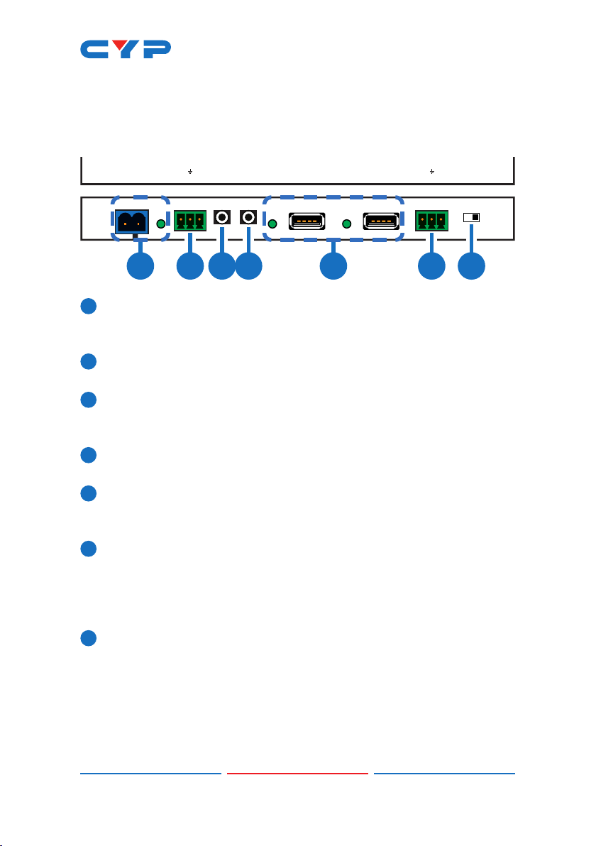
6.1 Front Panel
TX RXLR
DC 48V
+
-
OPT.
IN
POWER AUDIO OUT IR IN1 IR OUT2 USB USB UPDATERS-232 OUT
CAT5e/6/7 IN
HDMI OUTLAN
OPT.
IN
ARC
IN
2 3 4 5 6 71
1DC 48V & POWER LED: Plug the 48V DC power adapter into this
port and connect it to an AC wall outlet for power. The LED will
illuminate to indicate the unit is on and receiving power.
2AUDIO OUT: Connect to powered speakers or an amplier for
stereo analog audio output.
3IR IN 1: Connect to the provided IR Extender to extend the IR
control range of remotely located devices. Ensure that the remote
being used is within direct line-of-sight of the IR Extender.
4IR OUT 2: Connect to the provided IR Blaster to transmit IR signals to
devices within direct line-of-sight of the IR Blaster.
5USB: Connect to USB peripheral devices such as keyboard,
mouse, printer, ash drive, etc. for connection with the USB device
connected to the Transmitter.
6RS-232 OUT: Connect to the device you wish to control via a 3-pin
adapter cable to receive RS-232 commands from the Transmitter.
When sending commands to the Transmitter side, depending on
your equipment’s pinout, the Tx and Rx pins might need to be
reversed.
7UPDATE: This is reserved for rmware update use only. During
normal operation the dipswitch should be set to the right.

4
6.2 Side Panels
TX RXLR
OPT.
IN
POWERAUDIO OUTIR IN1IR OUT2 USBUSB UPDATERS-232 OUT
CAT5e/6/7 IN
HDMI OUTLAN
OPT.
IN
ARC
IN
TX RXLR
OPT.
IN
POWERAUDIO OUTIR IN1IR OUT2 USBUSB UPDATERS-232 OUT
CAT5e/6/7 IN
HDMI OUTLAN
OPT.
IN
ARC
IN
1 2 3 4 5
1LAN: Connect to an Ethernet supporting device or to your local
network as appropriate. The yellow LED will illuminate to indicate a
successful LAN connection between the Transmitter and Receiver
and will blink to indicate a data transmission. The green LED will
illuminate when the connected Ethernet speed is 100Mbit/s.
2OPT. IN: Connect to audio source equipment such as a media
player or PC to transmit the audio signal to the Transmitter’s OPT.
OUT port.
3ARC IN/OPT. IN: Allows you to switch between sending audio to
the Transmitter from the HDMI output’s ARC channel or from the
Receiver’s OPT. IN port.
Note: When ARC is enabled the maximum supported HDMI cable
length may vary. It is suggested to use cables under 2 meters long
to ensure the best audio quality.
4HDMI OUT: Connect to HDMI TVs, monitors or ampliers for digital
video and audio output.
5CAT5e/6/7 IN: Connect to the Transmitter unit with a single
Cat.5e/6/7 cable for transmission of all data signals. The yellow LED
will illuminate to indicate a successful data connection between
the Transmitter and Receiver. If the yellow LED blinks irregularly it
indicates a data link error. The green LED will illuminate to indicate
when PoH is active.

5
6.3 IR Cable Pin Assignment
3
2
1
IR Blaster
Power
IR Signal
NC
3
1
2
IR Signal
Power
Ground
IR Extender
Table des matières
Autres manuels CYP Alimentation


