Cumberland 300 Manuel utilisateur

PNEG-1945
IR Plus Feed Sensor
Installation and Operation Manual
PNEG-1945
Date: 02-27-15

2PNEG-1945 IR Plus Feed Sensor

Table of Contents
PNEG-1945 IR Plus Feed Sensor 3
Contents
Chapter 1 Safety .....................................................................................................................................................4
Cautionary Symbols Definitions .............................................................................................................4
Chapter 2 Application ............................................................................................................................................7
Chapter 3 Basic Operation ....................................................................................................................................8
Basic Operation for Swine ......................................................................................................................8
Basic Operation for Poultry ....................................................................................................................8
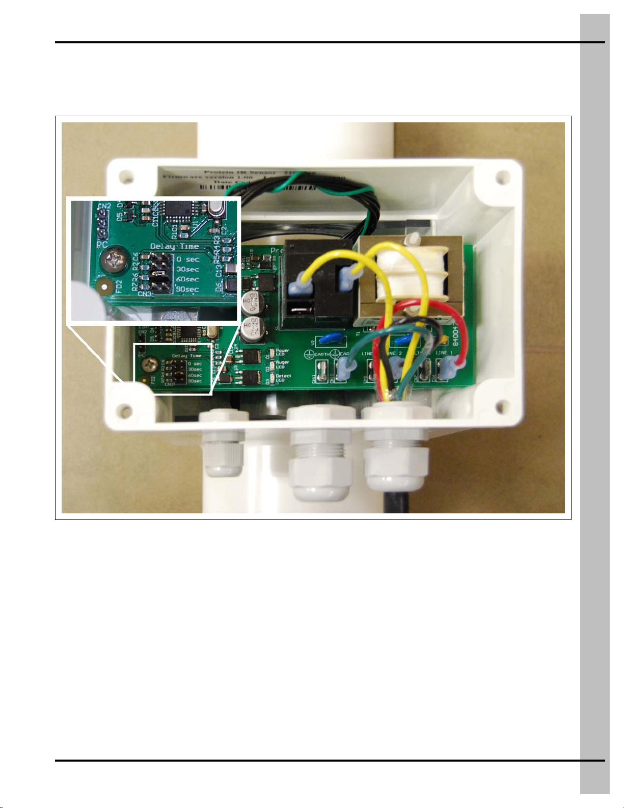
Chapter 4 Delay Time ............................................................................................................................................9
Chapter 5 Indicator LED Lights ..........................................................................................................................10
Chapter 6 Sensitivity ...........................................................................................................................................13
Chapter 7 Replacement Parts .............................................................................................................................14
IR Plus Feed Sensor Assembly (FLX-5262) ........................................................................................14
Chapter 8 Wiring Diagrams for Swine Application ...........................................................................................16
IR Plus Feed Sensor Used with Smart-Flex in Swine Application .......................................................16
Wiring Diagram for Smart-Flex to IR Plus Feed Sensor ......................................................................18
Wiring Diagram for IR Plus Feed Sensor to Smart-Flex ......................................................................19
Wiring Diagram for Relay Box ..............................................................................................................21
Chapter 9 Wiring Diagrams for Poultry Application .........................................................................................22
IR Plus Feed Sensor Hopper Level Control Model 350 .......................................................................22
IR Plus Feed Sensor Hopper Level Control Model 300 .......................................................................24
IR Plus Feed Sensor Wiring Diagram for Poultry Application ..............................................................26
Chapter 10 Warranty ............................................................................................................................................27

4PNEG-1945 IR Plus Feed Sensor
1. Safety
Cautionary Symbols Definitions
Cautionary symbols appear in this manual and on product decals. The symbols alert the user of potential
safety hazards, prohibited activities and mandatory actions. To help you recognize this information, we
use the symbols that are defined below.
NOTICE
DANGER
WARNING
CAUTION
This symbol indicates an imminently hazardous situation
which, if not avoided, will result in serious injury or death.
This symbol indicates a potentially hazardous situation
which, if not avoided, may result in serious injury or death.
This symbol indicates a potentially hazardous situation which,
if not avoided, may result in minor or moderate injury.
This symbol is used to address practices not related to
personal injury.
This symbol indicates a general hazard.
This symbol indicates a prohibited activity.
This symbol indicates a mandatory action.

1. Safety
PNEG-1945 IR Plus Feed Sensor 5
Follow Safety Instructions
• Carefully read and follow all safety messages in this
manual and safety signs on your machine. Keep signs
in good condition. Replace missing or damaged safety
signs. Replacement safety signs are available from
the manufacturer.
• Learn how to operate the machine correctly. Do not
operate without instruction.
• If you do not understand any part of this manual or
need assistance, contact your dealer.
Use Personal Protective Equipment
Eye Protection
Hearing Protection
Hand Protection
Head Protection
Respiratory Protection
Foot Protection
Fall Protection
• Use appropriate personal protective equipment:
• Wear clothing appropriate to the job.
• Remove all jewelry.
• Tie long hair up and back.

1. Safety
6PNEG-1945 IR Plus Feed Sensor
Install and Operate Electrical Equipment Properly
• Electrical controls should be installed by a qualified
electrician and must meet the standards set by the National
Electric Code, Canadian Electrical Code and all local and
state codes.
• Electrical components, wiring, conduit and junction boxes
must be suitable for temperatures in excess of 250°F (121°C).
• Disconnect and lock out all power sources before installing
wires/cables or servicing equipment.

PNEG-1945 IR Plus Feed Sensor 7
2. Application
In a swine application, the IR Plus Feed Sensor is used in conjunction with a Smart-Flex as the primary
control for a Flex-Flo feed line. It uses “INFRARED” technology to detect the presence of all types of
mash and pellet feeds. It is designed to be used in place of the proximity switch in a Smart-Flex control.
The sensor is installed underneath a Smart-Flex control unit between the powerhead drop (funnel) and
the drop tube at the end of a Flex-Flo feed system as shown in Figure 2A.
Figure 2A Swine
In a poultry application, the IR Plus Feed Sensor is used as a hopper level control to maintain the feed
level in one or more hoppers. It uses “INFRARED” technology to detect the presence of all types of mash
and pellet feeds. The sensor is installed under a drop kit and above each hopper of an incoming Flex-Flo
feed system as shown in Figure 2B.
Figure 2B Poultry
Ref # Description
AIR Plus Feed Sensors

8PNEG-1945 IR Plus Feed Sensor
3. Basic Operation
Basic Operation for Swine
The IR Plus Feed Sensor is connected to a Smart-Flex control unit and will immediately shut the
Flex-Flo auger system OFF when feed is full. When the feed falls away from the IR Plus Feed Sensor, it
will count down a pre-determined “Delay Time” and then turn the Flex-Flo auger system back ON when
the “Delay Time” has expired.
Basic Operation for Poultry
The IR Plus Feed Sensor is used as a hopper level control. It can be used alone or with multiple IR Plus
Feed Sensors connected together in parallel, to operate an incoming Flex-Flo auger. When all hoppers
are full of feed, the incoming Flex-Flo auger will shut OFF immediately. When the feed falls away from
at least one IR Plus Feed Sensor, it will count down a pre-determined “Delay Time” and then turn the
incoming Flex-Flo auger back ON when the “Delay Time” has expired.

PNEG-1945 IR Plus Feed Sensor 9
4. Delay Time
The “Delay Time” is adjustable inside the IR Plus Feed Sensor enclosure using a small pin jumper.
The “Delay Time” can be adjusted to 0 seconds or 30 seconds or 60 seconds or 90 seconds, depending
on the choice of the user. The factory default setting is 60 seconds. Place the pin jumper over the pins
next to the desired “Delay Time”. (See Figure 4A.)
Figure 4A Delay Time Jumper

10 PNEG-1945 IR Plus Feed Sensor
5. Indicator LED Lights
The IR Plus Feed Sensor is equipped with three (3) LED indicator lights on the PC board inside the
enclosure and also on the cover. These LED lights help to diagnose the condition of the IR Plus
Feed Sensor.
The top green LED indicates the state of electrical power to the sensor. When power to the sensor is
ON, this green LED will be illuminated. When power is OFF, the green LED will be OFF. (See Figure 5A
and Figure 5B.)
Figure 5A Power ON LED
Figure 5B Power ON LED
Ce manuel convient aux modèles suivants
1
Table des matières
Autres manuels Cumberland Accessoires


