CTD D45AX Manuel utilisateur

INSTRUCTION BULLETIN
& MAINTENANCE MANUAL
FOR CTD MODELS
D45AX & D45FX
CTD MACHINES
2382 E 48th Street
Vernon, CA 90058
(213) 689-4455 FAX (213) 689-1255
e-mail:ctdsaw@ctdsaw.com WWW: http://www.ctdsaw.com
05.2016
CTD MODEL NO:______________________
CTD SERIAL NO:______________________
MANUFACTURE DATE:________________
DISTRIBUTOR PURCHASED THROUGH:
(IF ANY)___________________________________________

INDEX
SUBJECT PAGE NO.
Machine Requirements................................................................................................................ 2
Installation and Set-Up................................................................................................................ 3
Electrical Installation................................................................................................................... 6
Air Pneumatics............................................................................................................................. 7
Safety Instructions....................................................................................................................... 11
How to Operate the Machine....................................................................................................... 12
Preventative Maintenance............................................................................................................ 15
Repair and Service....................................................................................................................... 16
D45FX Special Installation and Set-Up....................................................................................... 17
Spindle & Pivot Shaft Diagrams, Installation and Parts..................................................................... 18, 19
D45AX & D45FX Saw Head Assemblies ...................................................................................... 20, 21
D45AX Base & Air System Exploded View.................................................................................... 22
D45AX/FX Blade Guard Exploded View........................................................................................ 23
D45FX Stand Exploded View......................................................................................................... 24
New Style D45AX Pivot Exploded View......................................................................................... 25
OMD Exploded View...................................................................................................................... 26
Air Stop / Chip Breaker Exploded View........................................................................................... 27
Warranty......................................................................................................................................... 28
Machine Requirements:
MODEL NO: _____________________ SERIAL NO:______________________
Cutting Capacities:
Height Width
7/8”(22mm) 5-3/4”(146mm)
3-1/4” (83mm) 3”(76mm)
14” High Top (355mm) Blade Capacity
Height Width
2”(51mm) 6”(152mm)
3.25”(83mm) 3-1/2” (89mm)
-2-
Electrical Requirements: Based on two motors per machine
Motor Size Required Amperage Breaker Needed
2 H.P., 1 Phase 230 Volt 25 amps 40 amp
2 H.P., 3 Phase 230 Volt 10.8 amps 20 amp
2 H.P., 3 Phase 460 Volt 5.4 amps 15 amp
Pneumatic Requirements:
1 CFM per 10 strokes at 75 PSI (.043 cubic meters at 5.4 kg/cm2)
Dust Collection Requirements: 1200 CFM at 6” outlet
Cutting Tool Requirements: Heavy, rigid plate blades
10” blades: .090 to .100 plate 12” blades: .100 to .110 plate 14” blades: .120 to .130 plate
12” (305mm) Blade Capacity

-3-
Installation and Set Up:
CTD 12”, and 14” Models D45AX Automatic & D45FX Foot Cut Off Saws:
The CTD saw you have purchased is designed to cut wood, aluminum, and plastic, with of course, the proper
blade and conditions. For the material you are cutting, please refer to the cutting instructions for
each material type. The D45AX uses a NEMA 56 Frame 1-1/2 H.P., 3450 RPM, 60 HZ TEFC motor. CTD
uses a speed-up drive so that the blade will run at approximately 9500 SFPM on a 10” blade, and 11,400 SFPM
on a 12” blade. The D45AX and D45FX are exactly the same machine with the exception of the Air Pneumatic
System. All instructions will pertain to both machines unless specifically excluded.
IMPORTANT: Before operating saw, please be sure to read the “SAFETY INSTRUCTIONS TO THE OP-
ERATOR” (on Page No. 11).
Note: The floor stand must be shimmed, leveled and bolted to the floor or framed in to eliminate vibration.
Use holes provided in bottom of floor stand. All machines have been completely assembled at the factory,
then disassembled for shipment.
Space Requirements:
Assembly of Tables to Floor Stand:
1. Assemble leg to table with 3/8-16 bolts and nuts provided. Turn table upside down and attach leg to
table with leg rising vertically. Note: The hole in the table (when mounted properly) should be toward
the front of the table and far away from the blade to attach Fence Support Angle, P/N 15F82
(see Diagram “A”). If you have purchased a Vision Gage Assembly, be careful to protect lined measuring
gage.
2. Attach Table, P/N BF17 to machine floor stand on Angle Bracket, P/N BF05A. Use 3/8-16 bolts and
nuts provided on angle bracket.
Diagram “A”

Blade Installation:
Before setting blades on spindle, always shut off or disconnect air supply. With motor OFF and power
disconnected, remove blade guard by removing wing nuts on top of main blade guard. Also remove bolts located
at the front and sides of the blade guard. Remove main guard completely, by lifting off machine, exposing Arm
Assembly.
1. Remove Spindle Nut, P/N 15B1P36 or 37 and Outer Flange, P/N 150M13X. If necessary, hold blade in
hand with rag or lower blade into a piece of wood. Push down with a 15/16” wrench.
2. Place blade on spindle with tips pointing down. Make sure Slinger (inner flange P/N 150M14X) and blade
surface are clean before putting blade on spindle. This is a critical surface and is ground within.0005
flatness. Any debris or dust will wear this surface. Wipe both surfaces (blade and slinger) with a clean rag.
A. The blade must ALWAYS rotate to the rear of the machine on the underside of the blade
(see Diagram “D” on page No. 8).
Always check rotation before cutting a piece of material.
3. Replace Outer Flange, P/N 150M13X and nut
as before and tighten (refer to Diagram “B”).
Pull up with wrench. Do not over-tighten.
snugging the blade is all that is necessary.
If blades were purchased from CTD, your machine has
been set with your blades. If not, blade diameters may
vary. Check to see if the blades you are using conform
to Diagram “C”. If repositioning is necessary, follow
instructions below.
1. Position the arms so that the centerline of the
spindles are 2” above the table (see Diagram “D”).
A 1-1/2” thick spacer placed between the spindle nut flat and the table will bring the centerline up to 2”. It
is at this position that the two blades are the closest together.
2. Set blades as shown in Diagram “C” about 1/8” apart.
A. Loosen three hold down bolts on pivot bracket and move the entire arm and pivot assembly in or out of
its original position as needed in the keyway (see Diagram “E”).
B. Tighten three hold down bolts after positioning heads.
3. Use this method of setting blades ONLY. If blades are set at table level, they will contact each other on the
upstroke. This can cause severe damage to the blades.
Diagram “B”
Diagram “C”
Diagram “E”
-4-

Attaching Measuring System to Machine: (see specific instructions for the Measuring System purchased)
For: FEX, OMD, RAB, OMD/RAB Combination Gages, or PAS
1. Place long measuring gage on table with measuring tape facing up. Bolt through Front Fence Angle, P/N
15M36R with 3/8-16 bolts provided. Adjust gage so measurement rule is correctly set (see Diagram “G”);
A. With scale or ruler touching the side of the tips of the blade, measure a distance away from the blade.
Be sure the ruler and the tape on the fence gage read the same.
B. Adjust fence, left to right as necessary.
C. Both fences, left and right, must be in perfect alignment. Use a long straight edge for this purpose.
1. Take a two foot steel scale lying flat on table base. Butt edge forward against fences. Touch each
outside corner of scale. If one side pulls away from fence, then long fence is not in alignment with
left fence (see Diagram “F”).
D. Attach fence support angle to fence and table.
2. Place aluminum angle with slide into keyway. (Rabbet
Angle Assembly, P/N 15E85 is comprised of Slide,
P/N 15M80 & Rabbet Angle, P/N 15M85)
A. Move angle forward to front fence and square up.
B. When rabbet angle is square against front fence,
both measurement rules should read the same.
This may be visually deceiving.
Use a 90° square to check.
C. Adjust rabbet angle on slide as necessary by loosening 1/4-20 bolts on rabbet slide.
3. How to use Rabbet Gage:
A. Feed stick length with 45° mitre past right blade.
B. Slide aluminum angle under rabbet of wood moulding to desired dimension.
C. Move outside stop and clamp to that point and lock.
D. Slide rabbet angle back and cut.
-5-
Vision Gage Assembly:
The vision gage has been completely installed on your machine before shipment. It is then disassembled for
shipment.
1. Attach leg to table with 3/8-16 bolts and nuts provided.
2. Attach Table, P/N BF17C to machine floor stand on Angle Bracket, P/N BF05A. Use 3/8-16 bolts and nuts
provided on angle bracket.
3. Butt Vision Gage as close as possible to to the edge of the base casting P/N 15C20. Attach Vision Gage
to machine base with 10-32 screws provided.
A. With a scale or ruler touching the side of the tips of the blade, measure a distance away from the blade.
Be sure ruler and vision gage markings read the same. Adjust left to right as necessary.
4. Put outside Fence Gage, P/N 15BM223 on top of lined Vision Gage so that lines terminate at fence. Attach
outside measuring gage with 3/8-16 bolts provided to Right Front Fence Angle, P/N 15M36R. Adjust gage
so measurement rule is correct. Follow instructions under No. 3A above. Attach Fence Support Angle,
P/N 15F82 with bolt and nuts provided.
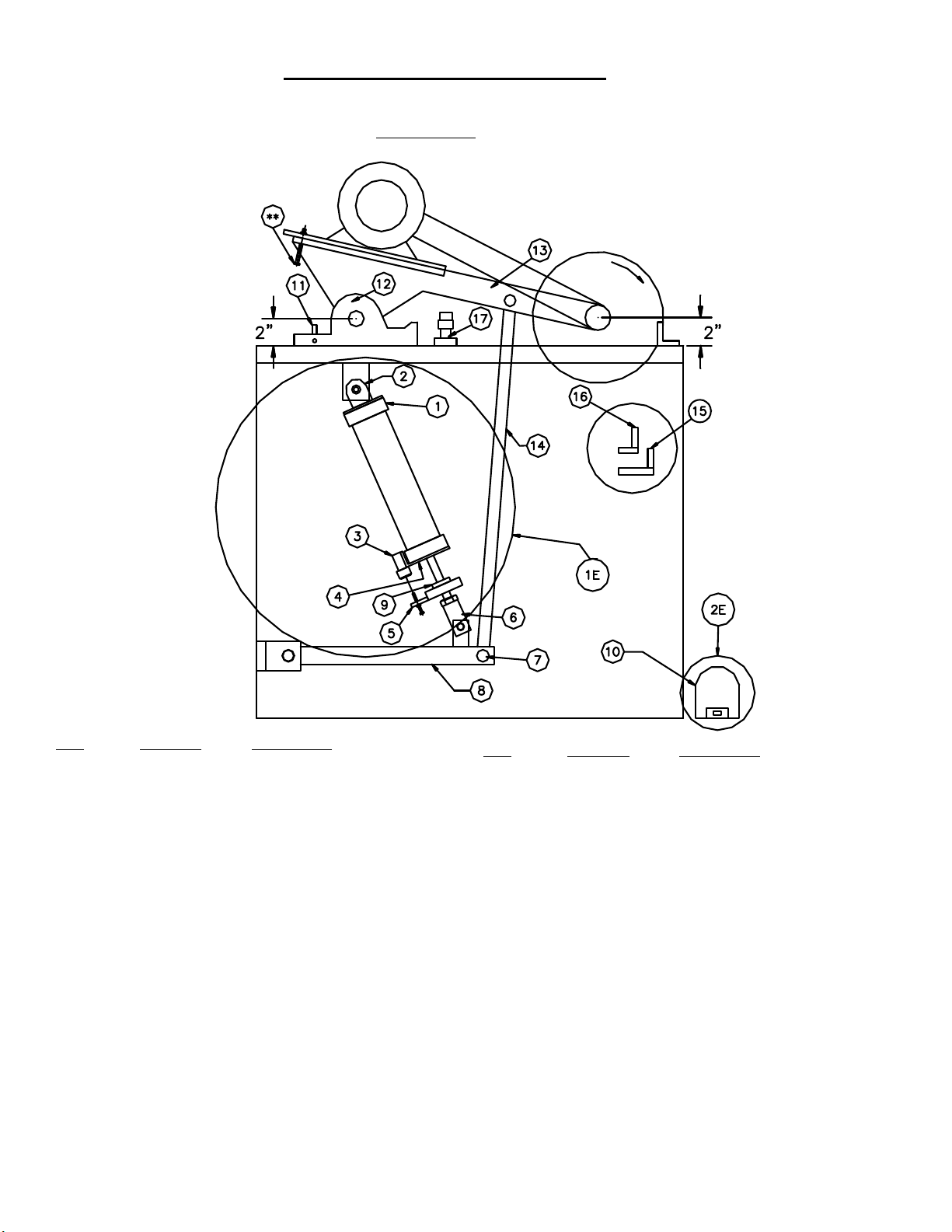
Diagram “F”
Diagram “G”

-6-
Vision Gage Diagram
Electrical Installation:
The CTD D45’s use two 2 H.P. single or three phase 3450 RPM, 60 HZ TEFC (totally enclosed fan cooled)
motors on a NEMA 56Z Frame. CTD uses a speed up drive so that the blade will run at approximately 3700 RPM.
Electrical installation should be performed by a qualified and certified electrician. A lock-out or disconnect switch
is located in front of the machine. It is a rotary switch to the left front of the machines. This disconnect switch is
used to shut off power to the machine and should be used whenever the blades are changed or at any time the
machine is serviced and the blades are exposed. A Dual Magnetic Starter, located inside the left side panel of the
machine protects the motor from overheating and will not allow the motor to restart itself after power outages or
undervoltage situations. The START button turns the motors “ON”. The STOP button turns the motor “OFF”.
Note: The STOP button must be pulled out before the START button will activate the motors.
I
f the blade guard is not set in place properly, the motors will not turn on. An interlock switch located below the
blade guard must be contacted before power is supplied to the starter.
Electrical Installation of Power to Starter by a Qualified Electrician:
All wiring from the motors to the starter has been completed and tested at the factory several times. The voltage
has been clearly tagged. DO NOT CONNECT ANY VOLTAGE THAT IS DIFFERENT THAN THE TAGGED
VOLTAGE, AS THIS MAY CAUSE SEVERE DAMAGE AND DANGER.. CONSULT FACTORY IF ANY
CHANGES ARE NEEDED.
Bring incoming power lines to the rear of the machine on left side using hard wire and dust proof connectors.
Attach incoming power lines through Floor Stand to the rotary disconnect switch. Connect to terminals 2 & 4
for single phase motors, and to terminals 2,4 & 6 for three phase motors. Always ground the green wire.
(See wiring diagram on Page 7.)
Single Phase Motor Replacement:
Connect motor leads to T1 and T3 of overload relay for single phase motors. (See wiring diagram for single
phase motors on following page) Green ground wire must be grounded to enclosure. If using type “SO” wire
and plug, use a dust tight connector through Floor Stand and a grounded plug. Be sure to check rotation. If a
change is necessary, open the motor box located on the motor, and switch the #8 and the #5 wires. This reverses
the rotation of a single phase motor. The blade must rotate down and to the rear on the underside of the blade
(see Diagram “D” on Page No. 8).

-7-
Three Phase Motor Replacement:
Connect motor line leads to T1, T2, & T3 of the overload relays. (See wiring diagram for three phase motors.)
Green ground wire must be grounded to enclosure. Be sure to check rotation as polarities may be different.
The blade must rotate down and to the rear on the underside of the blade (see Diagram “D” on Page No. 8). If a
change in rotation is necessary, reverse any two of the incoming power wires. Example: If the blades are running
backwards and incoming wires are connected White L1,Black L2,Red L3, switch the Black wire with the Red so
that Black is connected to L3 and Red is connected to L2. This will change the blades to rotate properly.
Motor Load Amperes Per Motor Circuit Breakers and Fuse Blocks
MOTOR SIZE 110 VOLT220 VOLT 440 VOLT 208/230 VOLT 460 VOLT
2 H.P., 1 Phase 25 amps 12.5 amps N/A QCD2060H -
2 H.P., 3 Phase N/A 5.4 amps 2.7 amps QCR3025H 15 amps Fuses
280 Volt Wiring Diagram
480 Volt Wiring Diagram

-8-
D45AX Air/Pneumatic System
Diagram “D”
Rotation
No. Part No. Description
1 153S71 CTD #3 Air Cylinder
2 153P27 Clevis Mount for Cylinder
3 B3P50 Way Normally Open Valve
4 4BF101 Valve Bracket
5 15M77 Upstop Block for Upstroke
Limit
6 15M26 Clevis Power Feed
7 15MS25A Front Pivot Shaft AX
8 15E30A/F Pivot Tube Assembly with tang
& shaft
9 157P73 Cylinder Bumper
10 B3P71 Way Spring Return Foot Valve
11 15M05 Eccentric Pin
**Upstroke Safety Bolt
Do not adjust! (for safety purposes only)
No. Part No. Description
12 15C002LX Pivot Bracket, Left
15C002RX Pivot Bracket, Right
3 15C001LX Arm Casting, Left
15C001RX Arm Casting, Right
14 15E27 Pull Rod Assembly
15 B3P60 Downstroke Control Valve
16 B3P60 Upstroke Control Valve
17 150B3P20 Downstop Bumper
150B1P20 Threaded Rod Bumper
1E 150E70 Air Cylinder Assembly
2E B3P71 Foot Valve Assembly

-9-
D45AX Air/Pneumatic System: (not for D45FX)
The air pneumatic system on the D45AX is simple to use and understand, and easy to operate. The main
components of the air system are shown below in the Air Circuit Piping Diagram. The system operates by
depressing the Foot Valve, P/N B3P71. This gives a signal to the main 4-Way Control Valve in the Foot Valve
to change the direction—allowing air to pass to the main drive Cylinder, P/N 153S71. This pushes the saw
heads down. The speed of descent is controlled by the Speed Control Valve, P/N B3P60. The saws reverse
when the Foot Valve is released. This signals the 4-way valve to change direction of air flow to the drive
cylinder and the saw heads reverse. See additional headings for operational components. Also refer to
Diagram “D” for parts listing of air components.
Diagram “I“ Air Circuit Piping for Model D45AX
Air Supply—The air supply must be turned off and all electrics disconnected before making adjustment on the
power feed. A working pressure of 75 PSI (5.4kg/cm2) is required. An industrial-type compressor of at least
3 CFM (.085 cubic meters) is recommended. An additional 3 CFM (.085 cubic meters is required for Spray
Mists. A conveniently located valve should be supplied by the user to shut off the air line. Arms should be
Raised or lowered by hand when setting up machine.
FR—An Air Filter/Regulator is installed ahead of the air inlet to the machine. This system helps
prevent foreign matter from entering the system. The FR is comprised of two different components.
1. The Air Filter Bowl is located on the left side and is provided with an automatic drain. This collects and
then releases foreign matter and condensation collected by the air filter.
2. The Pressure Regulator, which is located on top of the air filter, controls the amount of air pressure allowed
into the system. An operating pressure of 75 PSI is required. (This is set at the factory.)

Air Filter/Regulator
Foot Valve:
The Foot Valve, P/N B3P71 actuates the saw heads downward. Once the foot valve is depressed, it must be
held down. The stroke or downward movement of the saw heads can be reversed at any time by releasing on
the foot pedal. Since the Foot Valve rests on the floor, it is important to clean it regularly, as debris from
cutting can make its way into the valve, causing improper function. Do not maintain pressure on the Foot
Pedal, as the saw cannot reverse stroke.
Speed Control of Blades Movement:
The downstroke speed of the blades is controlled by the lower Speed Control Valve, P/N B3P60, No. 15. The
upstroke speed is controlled by the upper Speed Control Valve, P/N B3P60, No. 16. Both are located on the
right side of the floor stand and are connected to the main control 4-Way Valve. (See Diagram “D”) An easy
way to remember is the upstroke is controlled by the upper valve, and the downstroke is controlled by the lower
(down) valve. Up is up, and down is down.
Length of Stroke Adjustment:
The D45AX is unique in that the travel of the air cylinder can be adjusted to stroke only the length needed
to cut a particular moulding. Example: The highest moulding to be cut is 2” high. To adjust the stroke:
1. Shut off air supply and disconnect power.
2. Manually lower saw blades so that they are 1/2” above the work.
3. Adjust Upstop Clamp, No. 5 to contact Accessory Valve, No. 3 (see Diagram “D” on Page No. 8).
A. Loosen Upstop Clamp by using a 5/16 hex wrench on socket cap screw.
B. Move Upstop Block upward on cylinder shaft to contact Accessory Valve, closing the valve.
C. Tighten socket cap screw at this position.
4. The blades will now return to this height.
Adjust the Downstroke Bumper, No. 17 to contact Arm Casting, No. 13 as soon as the blades have cut
through the work.
You now have eliminated wasted motion and time, thereby increasing production. Always provide a safe dis-
tance between the blade and the work. Re-adjust the blade guard whenever the clamp is changed to make sure
the blades are completely covered.
-10-
Ce manuel convient aux modèles suivants
1
Table des matières
Autres manuels CTD Scie


