CSZ EZT-550 Manuel utilisateur

EZT-550 Controller
Instruction Manual
56121 REV B
8-05

EZT-550 Controller Manual
1
TABLE OF CONTENTS
1. Overview ................................................................................................................................. 4
1.1 Menu Bar Function Tree.......................................................................................................4
1.2 Touch Screen Interface ........................................................................................................ 6
2. Monitoring ................................................................................................................................. 7
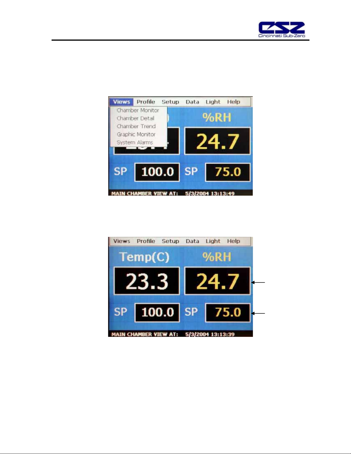
2.1 Chamber Monitor .................................................................................................................. 7
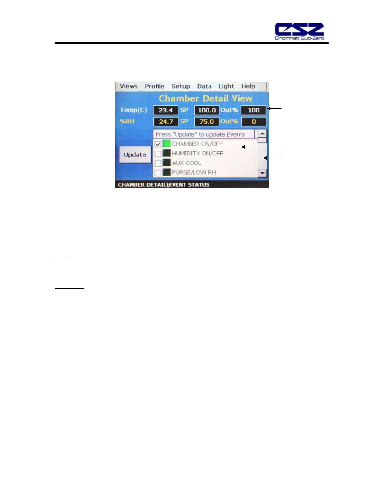
2.2 Chamber Detail..................................................................................................................... 8
2.3 Trend Graph ......................................................................................................................... 9
2.4 Graphic Monitor .................................................................................................................. 10
2.5 System Alarms.................................................................................................................... 10
2.6 Profile Status View.............................................................................................................. 11
3. Single Setpoint Operation......................................................................................................... 13
3.1 Single Setpoint Adjustment ................................................................................................13
3.2 Event Control (Chamber On/Off) ........................................................................................ 14
3.2.1 Chamber Options................................................................................................... 15
4. Profile Operation........................................................................................................................ 17
4.1 Profile Create/Edit............................................................................................................... 17
4.2 Guaranteed Soak Limits ..................................................................................................... 21
4.3 Plot Profile .......................................................................................................................... 22
4.4 Start/Stop Profile................................................................................................................. 23
4.4.1 Hold/Resume a Profile........................................................................................... 24
4.4.2 Advance Previous/Next Step................................................................................. 24
5. Chamber Setup .......................................................................................................................... 25
5.1 Control Tuning .................................................................................................................... 25
5.1.1 How to Adjust Tuning Parameters......................................................................... 27
5.2 Device Under Test (DUT) ................................................................................................... 28
5.3 Event Tag Names ............................................................................................................... 29
5.4 Power Recovery .................................................................................................................30
5.5 Timer Setup ........................................................................................................................ 31
5.6 Defrost Settings .................................................................................................................. 33
6. Datalogging ............................................................................................................................... 34
6.1 Start/Stop Datalogging........................................................................................................ 34
6.2 View Log File ...................................................................................................................... 35
6.2.1 Deleting Log Files.................................................................................................. 38
7. System Maintenance ................................................................................................................. 39
7.1 Set Date/Time..................................................................................................................... 40
7.2 Level 1 (User) Security Options.......................................................................................... 41
7.2.1 Degrees C/F Selection .......................................................................................... 41
7.2.2 Maintenance Counters .......................................................................................... 42
7.2.3 Calibration.............................................................................................................. 43
7.3 Factory Security Options ....................................................................................................50
7.3.1 Setpoint Limits ....................................................................................................... 50
7.3.2 Startup Configuration............................................................................................. 50
8. File Access ............................................................................................................................... 51
8.1 Opening Files...................................................................................................................... 51

EZT-550 Controller Manual
2
9. Communications........................................................................................................................ 53
9.1 Connecting a Computer to the EZT-550............................................................................. 53
9.1.1 RS-232 Serial Connection .....................................................................................53
9.2 Maintenance Protocol ......................................................................................................... 54
9.2.1 Write Data Command ............................................................................................ 55
9.2.2 Read Data Command............................................................................................ 57
9.2.3 BCC Block Check Calculation ............................................................................... 58
9.3 EZT-550 Operands .............................................................................................................59
9.3.1 Profile Area Operands ........................................................................................... 63

EZT-550 Controller Manual
3
Introduction
This manual has been tailored to match the specific features and options provided on the ZP(H) Series
chambers. Do not use this manual in an attempt to operate or maintain any other model chamber. It is highly
recommended that the end user read this manual thoroughly and understand all aspects of the chamber’s
operation prior to operating the chamber.
WARNING Warnings identify any condition or practice that, if not strictly observed, could result in
serious personal injury or possible loss of life.
CAUTION Cautions identify any condition or practice that, if not strictly observed, could result in
damage to, or destruction of, the system equipment.
Device Under Test (DUT) Protection
The chamber is equipped with high heat limits and/or safety devices. These devices are installed to protect the
chamber from exceeding design limits. These devices remove power from the chamber’s heaters ONLY and DO
NOT remove power from the device under test.
Provisions must be made by the end user to de-energize the tested device in the event of an over-temperature
condition. For this reason, the chamber is equipped with a DUT safety relay that should be connected to the
device’s power supply control circuit. In the event of an over-temperature condition, the relay will open and de-
energize the device under test to prevent a runaway thermal condition. See section 5.2 for more information on
the use of this safety feature.
Screen Displays
The graphic displays shown in this manual are based on ZPH Series chamber with the humidity option. Screens
displayed on temperature only chambers (ZP Series) will differ slightly from those shown. The temperature only
models will not include values or settings for humidity.

EZT-550 Controller Manual
4
1. Overview
The EZT-550 Controller is a not just another graphic interface for operating and monitoring the chamber. It is an
intelligent device that monitors and protects the chamber from adverse operating conditions. It does this without
the need for user intervention or knowledge on system operation. The displays provide the user with an intuitive
interface for navigating through the different menus and settings without having to go multiple levels deep in
screens like other “button style” systems. The EZT-550 provides a “Windows” like feel with drop down menus
and online help at all times. This section of the manual provides an overview of the menu items and structure.
1.1 Menu Bar Function Tree
The menu structure for the EZT-550 is as shown below:
Main Menu
Views: Chamber Monitor
Chamber Detail
Chamber Trend
Graphic Monitor
System Alarms
Profile: Edit/Monito
r
Views: Chamber Monitor
Profile Status
Profile Entry
Guaranteed Soak
Plot Profile
Edit: New profile
Insert/Delete Step
Copy/Paste Step
Select Profile
Save(as) Profile
Delete Profile
Run: Run profile
Hold Profile
Stop Profile
Advance Step

EZT-550 Controller Manual
5
Views: Chamber Monito
r
Data: Start/Stop Logging
Open Log File
Historical Trend
Li
g
ht: Li
g
ht On/Off
Hel
p
: Dis
p
la
y
S
p
ecific
Setup: Control Tuning
DUT Settings
Event Tagnames
Power Recovery
Timer Setup
Defrost Settings
System Maintenance
Setu
p
: Chambe
r
S
y
stem Maintenance Views: Chamber Setu
p
Setup: Degrees C/F
Maintenance Counters
Password Entry
Setpoint Limits
Set Date/Time
Startup Configuration
Calibration: Analog Input 1
Analog Input 2
Analog Input 3
Analog Input 4
Analog Out 1
Analog Out 2

EZT-550 Controller Manual
6
1.2 Touch Screen Interface
The EZT-550 display is divided into three main sections; the menu bar, main display area and detail window.
Menu Bar: The menu bar is used to navigate through the various monitoring and control screens.
Main Display Area: The main display area contains the active items for the menu item selected.
Detail Window: The detail window provides display specific information.
To select items on the display, simply touch the desired text or numerical entry item. Do not use any sharp or
metal objects on the touch screen as they will damage the interface. For detailed information regarding the
different screen elements, see the following sections.
Menu Bar
Detail Window
Main Display
Area

EZT-550 Controller Manual
7
2. Monitoring
The chamber monitoring screens provide various means of verifying chamber operation and performance. The
displays are accessed from the main menu under “Views”.
2.1 Chamber Monitor
The monitor screen displays the current setpoints and process variables. The setpoints can be modified from
this screen by touching the setpoint field box. Upon pressing the setpoint field box, the pop-up numeric entry
pad will appear from which the setpoint can be entered. However, if a profile is running or the timer is enabled,
the setpoint fields are locked out from user adjustment.
Process Variables
Setpoints

EZT-550 Controller Manual
8
2.2 Chamber Detail
The chamber detail screen includes additional operating parameters beyond the setpoint and process variables
shown on the monitor screen. The chamber events can be activated or de-activated from this screen and their
current status can be monitored. As on the monitor screen, the setpoints can also be changed from the detail
screen when a profile is not active and the timer is disabled.
Special Fields Description
Out%
The output field shows the amount of heating or cooling (humidifying or dehumidifying) that is being done
expressed in terms of percent. The display range is from –100 to 100% representing full cooling to full heating
for example. A reading of zero means that no cooling or heating is being performed.
Event Table
The events are used to control specific chamber functions and optional customer relays. Not all events are used
with the ZP(H) Series chamber and are marked as such. The scroll bar to the right of the list box allows the user
to view each event through the list.
Next to each event is a check box and indicator light. The check box indicates which events are selected to turn
on. The indicator light next to each event shows the status of that event. A green light indicates that the event is
on while a dark indicator represents an off status.
Percent Output
Event Table
Scroll bar

EZT-550 Controller Manual
9
2.3 Trend Graph
The trend graph displays the setpoint and process variable history over a period of time. The vertical axis
determines the range of displayed data while the horizontal axis determines the sample period. The maximum
time period allowable is 4 hours.
Trend Configuration
To adjust the displayed variables, range and sampling period, touch the “Trend Setup” button. The Trend Setup
screen will appear with the available adjustment controls.
Trend Zero
The zero value sets the minimum range of the vertical access for the trend variables.
Trend Span
The span value sets the maximum range of the vertical access for the trend variables.
Time(Mins)
The time interval is in minutes and adjusts the displayed time period for the trend. The allowable range is from
10 to 240 minutes.
Table des matières
Autres manuels CSZ Contrôleurs


