Crystal Vision Demon 2 Manuel utilisateur

Crystal Vision Ltd., Lion Technology Park, Station Road East, Whittlesford, Cambridge, CB22 4WL, England.
E-mail: [email protected] Website: www.crystalvision.tv Tel: +44(0) 1223 497049 Fax: +44(0) 1223 497059
Demon 2
12 bit de-embedding monitor

Demon 2 User Manual R1.4 Crystal Vision
Demon 2 User Manual R1.4 107/09/2012
Contents
1Introduction 3
2Hardware installation 5
2.1Demon 2 configuration 5
Changing sync level 6
Selecting SDI/analogue outputs 6
Adjusting analogue gains 6
2.2Rear modules and signal I/O 7
Rear module connections with RM04: 7
Rear module connections with RM06: 8
Rear module connections with RM22: 9
Rear module connections with RM36: 9
Rear module connections with RM05: 11
2.3General Purpose Interface (GPI) 13
4U frame GPI connections 15
2U frame GPI connections 16
1U frame GPI connections 16
Indigo DT desk top box GPI connections 17
3Card edge operation 18
General status and audio group select 19
Using presets 20
Setting video parameters 20
Routing audio channels 21
Using GPI lines 23
Defaults 24
4Using the active front panel 25
4.1Module selected 25

Demon 2 User Manual R1.4 Crystal Vision
Demon 2 User Manual R1.4 207/09/2012
Updating the display 27
4.2The Demon 2 active panel menu structure 27
Demon 2 Menu Structure 28
Video Control Menu 29
Audio configuration menu 30
Configuring GPIs 31
Status 33
5Statesman 34
5.1Statesman operation 34
Video Controls 35
Audio Controls 36
Headphone monitor 37
GPI and Preset controls 37
Toolkit 38
6Trouble shooting 40
Basic fault finding guide 40
7Specification 42
Revision 1 RM36 information added. 16/03/07
Revision 2 RM36 connection information amended 09/01/08
Revision 3 Specifications updated 23/02/12
Revision 4 RM04 label details changed, page 7. 08/08/12

Crystal Vision Introduction
Demon 2 User Manual R1.4 307/09/2012
1 Introduction
Demon 2 is a de-embedding monitor designed for applications requiring the simultaneous
monitoring of video and embedded audio that can convert incoming SDI with embedded
audio into combinations of component, composite, Y/C and SDI distribution, along with
20 bit AES and analogue audio.
The on-board 12-bit monitoring video encoder can be configured to produce a variety of
video outputs. The four output formats available from the encoder are GBR with sync on
all, YUV with sync on Y, S-video and composite in either 625 line or 525. A combination
of these outputs will be available depending on Mode and rear module selection.
Demon 2 de-embedding monitor
Analogue video outputs may also be substituted for up to four non-reclocked SDI input
loop-throughs.
Any one of the four audio groups contained in the SDI stream can be de-embedded and
the resulting four channels of audio then be routed to any of the four audio outputs.
The output audio is available simultaneously as four mono (two stereo) balanced analogue
and two balanced or unbalanced AES, depending on the rear module. Audio monitoring is
available via the mini headphone socket located on the front board edge.
Sixteen presets allow you to store and recall parameters such as video output
configurations, audio routing and audio group selection.

Crystal Vision Introduction
Demon 2 User Manual R1.4 407/09/2012
Demon 2 uses the same sophisticated techniques employed in TANDEM to protect and
minimise the effects of cuts to untimed and asynchronous SDI, SDI corruption and TRS
loss in the SDI signal. The Demon 2 will also report a frozen or black video input and
EDH errors.
The main features are as follows:
SDI audio/video monitoring encoder
Up to five simultaneous video outputs – RGB, YUV, Y/C, Composite and SDI
depending on rear module and link selection.
Automatic 525/625 input switching
Video error detection and alarm
Sophisticated error handling of upstream input switching
Simultaneous analogue and AES/EBU audio outputs from any one incoming embedded
audio group
4 x 4 audio router to select any de-embedded channel to any output
Dedicated headphone monitoring socket
Flexible yet simple remote control and/or board edge control
Sixteen presets recallable by GPIs and Demon control
Demon 2 is a 100mm x 266mm module, which fits in all standard frames and can be
integrated with any boards from the company’s full product range.
Demon 2 can be used with the RM04, RM05, RM06, RM22 and RM36 frame rear
modules, depending on the packing density and outputs required. SDI input loop-
through/analogue video outputs are selected by movable links on the board.
Demon 2 is particularly ideal for multi-channel broadcasters faced with many embedded
feeds to monitor, or for applications needing to de-embed both analogue and digital audio
at the same time. Demon 2 can also be incorporated with an Indigo DT desktop box to
drive a plasma or CRT display and active speakers for local audio de-embedding and
extraction of analogue video.
Crystal Vision Hardware installation
Demon 2 User Manual R1.4 507/09/2012
2Hardware installation
The Demon 2 single height module can be used with the RM04, RM05, RM06, RM22
and RM36 rear connectors that will fit into all Crystal Vision rack frames (RM05 – not
1U frames). All modules can be connected or removed while the frame is powered,
without damaging the board.
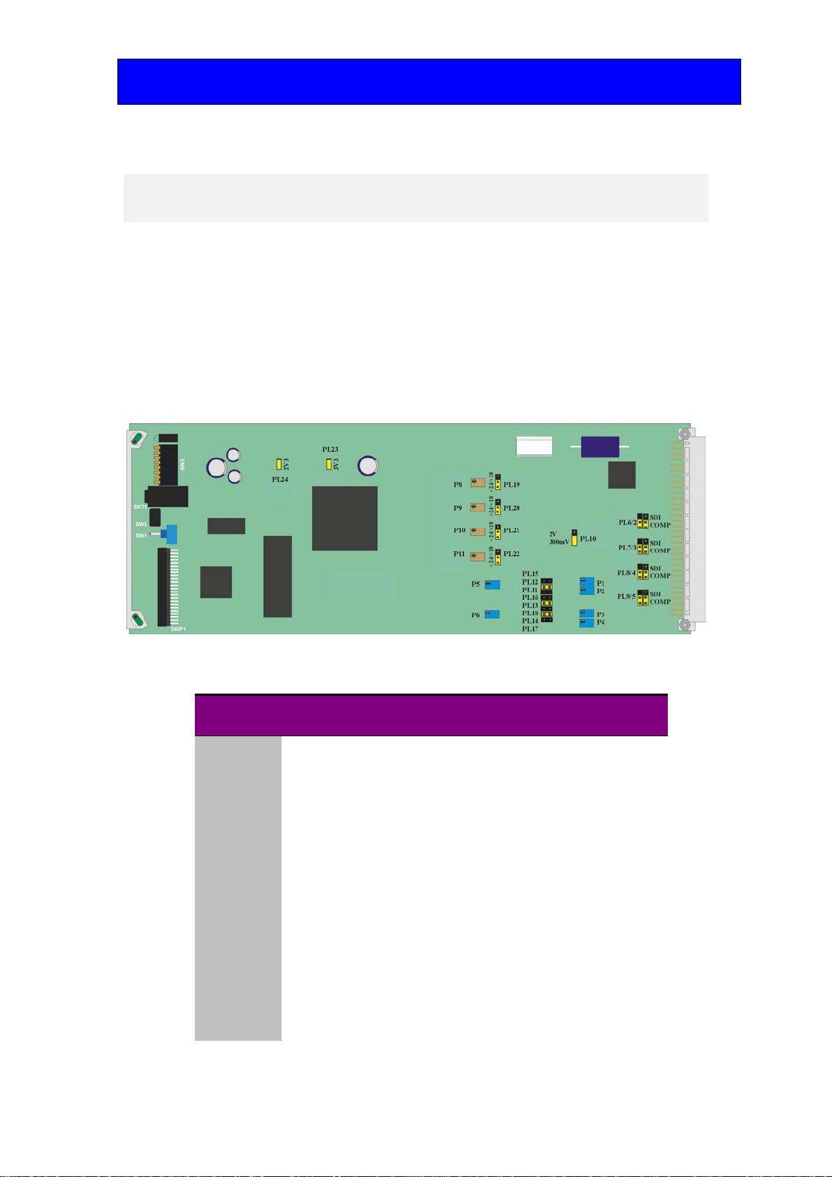
2.1 Demon 2 configuration
Demon 2 board showing configuration jumpers
Link positions (Video)
Link Function Link 1-2 Link 2-3
PL10 Video sync level 300mV p-p into 75approx2V p-p into
75
*PL6/2 O/P2 select Analogue SDI loop-through
*PL7/3 O/P4 select Analogue SDI loop-through
*PL8/4 O/P5 select Analogue SDI loop-through
*PL9/5 O/P3 select Analogue SDI loop-through
PL15 O/P1 configure YC-Y
PL12 O/P1 configure CVBS
PL11 O/P1 configure G/Y
PL16 O/P2 configure YC-C
PL13 O/P2 configure CVBS
PL18 O/P2 configure B/U
PL14 O/P3 configure CVBS
PL17 O/P3 configure R/V
Note: *Links marked with an asterisk are double links and care must be taken to ensure correct
orientation.

Crystal Vision Hardware installation
Demon 2 User Manual R1.4 607/09/2012
Link positions (Audio)
Link Function Link 1-2 Link 2-3
PL19 Ch1 Gain +18dBu +24dBu
PL20 Ch2 Gain +18dBu +24dBu
PL21 Ch4 Gain +18dBu +24dBu
PL22 Ch3 Gain +18dBu +24dBu
Changing sync level
The output sync can be changed from the default of 300mV to approximately 2V for
component modes that require large syncs with board link PL10. Place PL10 in the upper
position for 2V and the lower position for 300mV.
Selecting SDI/analogue outputs
On rear connectors that support O/P 2, O/P 3, O/P 4 or O/P 5, either SDI or analogue
video can be selected for each output with link pairs as shown in the link position
summary table above. Output 1 is always Analogue and cannot be configured for SDI.
Adjusting analogue gains
The following gain adjustments are provided:
Variables
P5 & 6 Analogue Video calibrate (factory set, not user adjustable)
P1 O/P 1 calibrate (factory set for 1.0V)
P2 O/P 2 calibrate (factory set for 1.0V)
P3 O/P 4 calibrate (factory set for 1.0V)
P4 O/P 3 calibrate (factory set for 1.0V)
P8 Analogue Audio Channel 2 Gain (factory set for =18dBu)
P9 Analogue Audio Channel 2 Gain (factory set for =18dBu)
P10 Analogue Audio Channel 3 Gain (factory set for =18dBu)
P11 Analogue Audio Channel 4 Gain (factory set for =18dBu)
Note: All gains have been factory set and should not require any further adjustment.

Crystal Vision Hardware installation
Demon 2 User Manual R1.4 707/09/2012
2.2 Rear modules and signal I/O
The Indigo 4 4U frame takes up to 24 single height Crystal Vision modules, 12 single
height modules will fit in the Indigo 2 2U frame, six single height modules will fit in the
Indigo 1 1U frame and two will fit in the Indigo DT desk top box.
There are five types of rear connector available for the Indigo frames to provide system
flexibility by allowing a mix between access to all connections and maximum module
packing density.
Rear module connections with RM04:
RM04. Fits in all frames Description
RM04
Up to 24 modules may be
fitted in a single frame.
All frame slots can be used
RGB YUV YC CBVS
SDI IN SDI In SDI In SDI In SDI In
OUT A (O/P 1) G Y YC-Y CVBS
OUT B (O/P 2) B U YC-C CVBS / SDI loop
OUT C (O/P 3) R V CVBS / SDI loop CVBS / SDI loop
RM04 Audio Out Hi Density 26-way D-Type Connector
1 GND 8 Ch4+ 15 Sync 22 nc
2 Ch1+ 9 GND 16 AES1- 23 GND
3 Ch1- 10 AES2+ 17 AES1+ 24 GND
4 Ch2+ 11 nc 18 Ch4- 25 nc
5 Ch2- 12 AES2- 19 GND 26 nc
6 Ch3+ 13 AES2+ 20 GND
7 Ch3- 14 AES1+ 21 nc
Crystal Vision Hardware installation
Demon 2 User Manual R1.4 807/09/2012
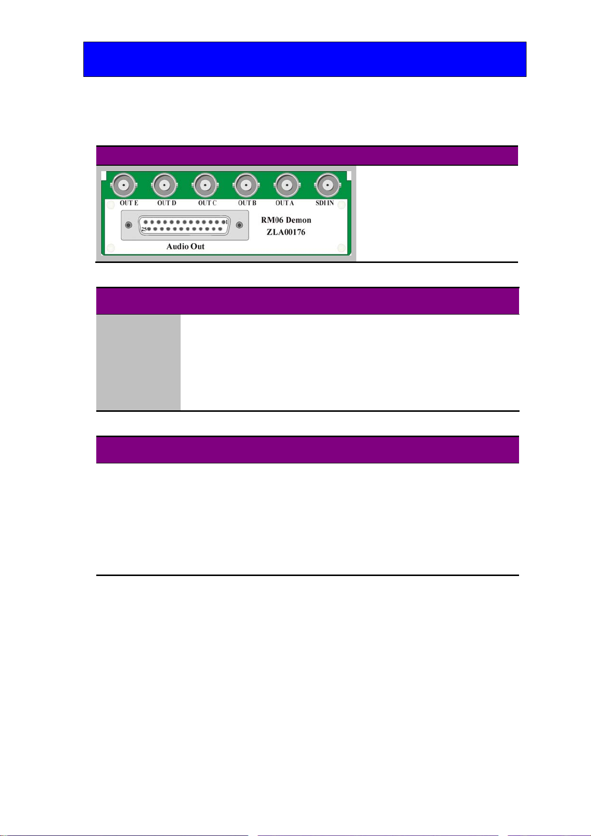
Rear module connections with RM06:
RM06. Fits in all frames Description
RM06 (ZLA00176 artwork)
12 modules per 4U frame, 6 per
2U frame, 3 per 1U frame and 1
per DTB
1 module per rear connector
6 connections available
Card fits in upper slot
No card fits in lower slot
RGB YUV YC CBVS
SDI IN SDI In SDI In SDI In SDI In
OUT A (O/P 1) G Y YC/Y CBVS
OUT B (O/P 2) B U YC-C CVBS / SDI loop
OUT C (O/P 4) CVBS / SDI loop CVBS / SDI loop CVBS / SDI loop CVBS / SDI loop
OUT D (O/P 3) R V CVBS / SDI loop CVBS / SDI loop
OUT E (O/P 5) CVBS / SDI loop CVBS / SDI loop CVBS / SDI loop CVBS / SDI loop
Audio Out 25-way D-Type Connector
1 GPI1 8 Ch4+ 15 GPI4 22 AES2+
2 GPI3 9 AES1+ 16 GPO2 23 nc
3 GPO1 10 Sync 17 GND 24 AES2-
4 GND 11 AES1- 18 Ch1+ 25 AES2+
5 Ch2+ 12 AES1+ 19 Ch1-
6 Ch2- 13 GND 20 Ch3+
7 Ch4- 14 GPI2 21 Ch3-

Crystal Vision Hardware installation
Demon 2 User Manual R1.4 907/09/2012
Rear module connections with RM22:
RM22. Fits in all frames Description
RM22 (ZLA00186 artwork)
12 modules per 4U frame, 6 per
2U frame, 3 per 1U frame and 1
per DTB
1 module per rear connector
6 connections available
Card fits in upper slot
No card fits in lower slot
RGB YUV YC CBVS
SDI IN SDI In SDI In SDI In SDI In
OUT A (O/P 1) G Y YC-Y CVBS
OUT B (O/P 2) B U YC-C CVBS / SDI loop
OUT C (O/P 3) R V CVBS / SDI loop CVBS / SDI loop
OUT D (O/P 4) CVBS / SDI loop CVBS / SDI loop CVBS/SDI loop CVBS / SDI loop
OUT E (O/P 5) CVBS / SDI loop CVBS / SDI loop CVBS / SDI loop CVBS / SDI loop
AES2 AES2 AES2 AES2 AES2
AES1B AES1B AES1B AES1B AES1B
AES1A AES1A AES1A AES1A AES1A
Sync Out Sync Out Sync Out Sync Out Sync Out
Audio Out 15-way D-Type Connector
1 GND 5 Ch1+ 9 nc 13 Ch2-
2 nc 6 Ch2+ 10 nc 14 Ch4+
3 nc 7 Ch3+ 11 GND 15 Ch4-
4 GND 8 Ch3- 12 Ch1-
Rear module connections with RM36:
The RM36 is an “easywire” alternative to the RM06. Both rear modules share common
video connections but the RM36 uses a DIN 41612 connector in place of the D-Type
connector found on the RM06.
RM36. Fits in all frames Description
RM36
12 modules per 4U frame, 6 per
2U frame, 3 per 1U frame and 1
per DTB
1 module per rear connector
6 connections available
Card fits in upper slot
No card fits in lower slot
Table des matières


