Crown Com-Tech CT-1610 Manuel utilisateur

102539-1
2/98
R.S.V.P.
Remote Switching Voltage Provider
© 1998 by Crown International, Inc., P.O. Box 1000, Elkhart, IN
46515-1000 U.S.A. Telephone: 219-294-8000. Fax: 219-294-8329.
Trademark Notice:
Crown
®is a registered trademark of Crown
International, Inc. Other trademarks are the property of their
respective owners.
®
120 VAC North
American
Units Only:
Commercial
Audio
E106377

R.S.V.P. Remote Switching Voltage Provider
Page 2
Printed on
recycled paper.
WARNING
TO REDUCE THE RISK OF
ELECTRIC
SHOCK, DO NOT EXPOSE THIS
EQUIPMENT TO RAIN OR
MOISTURE!
The information furnished in this manual does not include all of the
details of design, production, or variations of the equipment. Nor
does it cover every possible situation which may arise during instal-
lation,operationormaintenance.Ifyouneedspecialassistancebe-
yondthescopeofthismanual,pleasecontactourTechnicalSupport
Group.
Crown Audio Division Technical Support Group
Plant 2 SW, 1718 W. Mishawaka Rd., Elkhart, Indiana 46515 U.S.A.
Phone: 800-342-6939 (North America, Puerto Rico and Virgin Islands) or 219-294-8200
Fax: 219-294-8301
Fax Back (North America only): 800-294-4094 or 219-293-9200
Fax Back (International): 219-294-8100
Internet:http://www.crownaudio.com
C A U T I O N
RISK OF ELECTRIC SHOCK
DO NOT OPEN
TO PREVENT ELECTRIC SHOCK DO
NOT REMOVE TOP OR BOTTOM
COVERS. NO USER SERVICEABLE
PARTS INSIDE. REFER SERVICING
TO QUALIFIED SERVICE
PERSONNEL.
A V I S
RISQUE DE CHOC ÉLECTRIQUE
N’OUVREZ PAS
À PRÉVENIR LE CHOC ÉLECTRIQUE
N’ENLEVEZ PAS LES COUVERCLES. IL
N’Y A PAS DES PARTIES
SERVICEABLE À L’INTÉRIEUR. TOUS
REPARATIONS DOIT ETRE FAIRE PAR
PERSONNEL QUALIFIÉ SEULMENT.
Lightning Bolt Symbol:
This symbol is used to alert
the user to the presence of
dangerous voltages and the
possible risk of electric
shock.
Exclamation Mark Sym-
bol:
This symbol is used to alert
the user to make special note
of important operating or
maintenance instructions
found in the reference
manual.
Watch for these symbols:

R.S.V.P. Remote Switching Voltage Provider
Page 3
1 Welcome
Thank you for purchasing the Crown
R.S.V.P.
(Remote Switching Voltage
Provider) accessory module, de-
signed for use with Crown’s CT-10
series amplifiers. The
R.S.V.P.
takes
advantage of Crown’s CT-10 series’
soft-start feature, eliminating the
need for expensive sequencing
equipment or complicated startup
routines.
Using Crown’s
R.S.V.P.
module, you
can control the power-up/power-
down function of your CT-10 series
amplifier from across the room—or
across the stadium. Each
R.S.V.P.
unit controls 21 amplifier remote
jacks. That’s enough to control a 6-
foot (1.83 meter) rack of amplifiers
and still have one jack left over to
chaintoanother
R.S.V.P.
Unitsarein-
dividually powered, allowing you to
daisy-chain any number of
R.S.V.P.
s
for remote control of an unlimited
number of amplifiers.
Power-up/power-down can be con-
trolled using an auxiliary device
(such as an
IQ System
) via the aux
port, or through the use of a pair of
momentary switches. Remote mo-
mentary switches can be connected
inparallel,soyour amps can be con-
trolled from various locations: front of
house, backstage, lighting booth,
and so on. With a maximum switch-
ingdistanceofupto2000feet(609.6
meters) per unit, the
R.S.V.P.
can
provide on/off capabilities any-
where—oreverywhere—youneed it.
Figure 1.1
R.S.V.P.
top view
Figure 1.2
R.S.V.P.
left side view

R.S.V.P. Remote Switching Voltage Provider
Page 4
Feature Summary
❏Takes advantage of CT-10 series’ soft-start feature, eliminat-
ing the need for expensive sequencing equipment.
❏Provides remote power-up/power-down of systems via a
simple momentary switch closure.
❏Optional
IQ System
control for added security.
❏Units are individually powered and can be daisy-chained to
control a limitless number of amplifiers.
❏Each unit directly controls up to 21 amplifiers.
❏Convenient connection system uses RJ-11 connectors for
quick and easy, cost-effective installation.
R.S.V.P. Remote Switching Voltage Provider
Page 5
2 Facilities
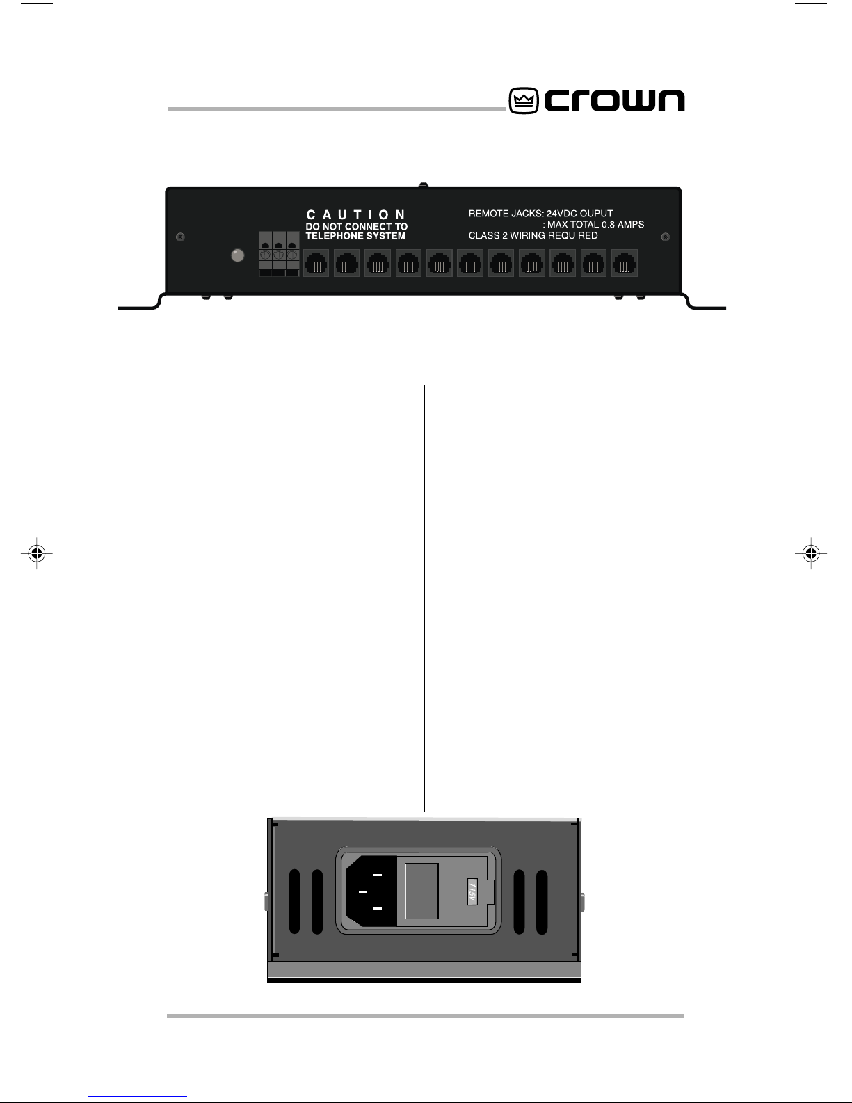
A. Enable Light
Green LED located on the left side
panel that indicates low voltage sup-
ply operation.
B.On/Com/Off
On, common, and off barrier block
input located on the left front panel
for connection of remote momentary
switches.
C. Slave/Aux In Port
RJ-11 connector located on the left
sidepanel thatallowscontrolfrom an
IQ System aux port. Also used for
daisy-chaining
R.S.V.P.
units to-
gether.
D. To Amplifier Remote
RJ-11 connectors located on the left
and right side panels for connecting
to CT-10 series amplifiers or daisy-
chained
R.S.V.P.
units. (See Figures
3.2 and 3.3) Each
R.S.V.P.
can con-
trol 21 separate CT-10 series amplifi-
ers, or the
R.S.V.P.
can be
daisy-chained to other
R.S.V.P.
units
to provide control over an unlimited
number of amplifiers. RJ-11 connec-
tors are available from the Crown
Parts Department (219-294-8200).
E. AC Power Inlet
Standard IEC “three prong” AC con-
nector located on the back panel.
F. Fuse Access Door
Located on the back panel, this al-
lows access to the fuse in the event
that it needs to be changed. Please
refer to section 7.1 on changing the
fuse before trying to access this
area.
Figure 2.1 Left Panel Facilities
Figure 2.2 Rear Panel Facilities

R.S.V.P. Remote Switching Voltage Provider
Page 6
3 Installation
This section will give the necessary
information for installing the
R.S.V.P.
into your equipment rack. It will also
provide ways to incorporate the
R.S.V.P.
into your system. Please
read this section thoroughly, as the
R.S.V.P.
has special cooling and
mounting requirements.
3.1 Cooling
Make sure that the vent holes of
the
R.S.V.P.
are NOT obstructed.
When mounting the unit in the back
of your rack, avoid blocking air flow
to all of your rack-mounted equip-
ment
.
3.2 Mounting
The
R.S.V.P.
is designed to be
mounted in the REAR of a standard
19-inch (48.3-cm) equipment rack.
Placing it in the back of the rack pro-
vides a more tamper-resistant loca-
tion and allows for easier access to
equipment.Fourkeyholes on the unit
can accomodate up to a #10 screw.
For a more secure installation, four
0.2- inch (0.5-cm) holes are also
available.
.
3.3 Wiring for Amplifiers
Convenient RJ-11 connectors link
the
R.S.V.P.
to the remote CT-10 se-
ries amplifiers. Please note that the
RJ-11jacksare polarity sensitive. Pin
4 must be grounded, and Pin 3 must
be supplied with a positive voltage
pull up (positive with respect to
ground). Refer to Figure 3.1 for RJ
jack pin assignments.* The maxi-
mum signal that can be exposed to
theRJ-11jacksis35VDCor25VAC.
(RJ-11connectors areavailablefrom
the Crown Parts Department.)
Figure 3.2 shows one possible sys-
tem configuration using the
R.S.V.P.
andarackofCT-10seriesamplifiers.
Runs of less than 30 feet (9.15
meters) between the
R.S.V.P.
and
the amplifiers are required for the
R.S.V.P.
to function properly. Up to
21 CT-10 series amplifiers can be
controlled from a single
R.S.V.P.
However, daisy- chaining together
units, as shown in Figure 3.3, can
provide for an unlimited number of
amplifiers in a system.
* The mating connector for the
R.S.V.P.
RJ-11 jack contains 4 contact pins in a 6-slot
case, as shown. For additional information please contact your local dealer or
Crown Technical Support.
Figure 3.1 RJ-11 connector pin assignments

R.S.V.P. Remote Switching Voltage Provider
Page 7
Figure 3.2 System Configuration—
R.S.V.P.
to CT-10 Series

R.S.V.P. Remote Switching Voltage Provider
Page 8
Figure 3.3 System Configuration—multiple
R.S.V.P.s wired in a bus configuration

R.S.V.P. Remote Switching Voltage Provider
Page 9
Figure 3.4 System configuration with several
R.S.V.P.
s wired in a bus configuration
Figure 3.5 System configuration with several
R.S.V.P
.s in a “star” configuration

R.S.V.P. Remote Switching Voltage Provider
Page 10
3.4 Daisy-Chaining Multiple
R.S.V.P.
Units Together
You’ll need standard cable with RJ-
11 connectors to daisy-chain mul-
tiple
R.S.V.P.
units together. (Refer to
Section 3.3 for information on the RJ-
11 connectors.) To slave
R.S.V.P.
units, connect one end of the cable
from one of the “To Amplifier Re-
mote” ports on the
R.S.V.P.
unit
which will be configured as the mas-
terunit.*Connecttheotherendofthe
cable to the “Slave/Aux In” port on
the remote unit. This run can be as
long as 2000 feet (609.6 meters), al-
lowing control of several systems
from one location.
See Figure 3.3 for a sample system
configuration when daisy-chaining
multiple
R.S.V.P.
s. Figure 3.4 shows
several units in a bus configuration,
while Figure 3.5 shows how to set up
a star configuration using several
R.S.V.P.
s.
* Note: The unit selected to be master will be wired to receive the power-up/power-
down signal from momentary switches via the On/Com/Off connectors, or from an
attached IQ System via the Slave/Aux In port.
3.5 Wiring for Remote
Control via the “Slave/Aux
In”Port
In addition to providing for daisy-
chaining of
R.S.V.P.
units, the “Slave/
Aux In” port also allows for control of
yoursystem to be providedusing an
IQ System
via the IQ Aux port (see
Figures 3.6 and 3.7). In fact, the sys-
tem can be controlled by a variety of
auxiliaryunitsaslongastheyprovide
10-35 VDC or 10-25 VAC output.
Simply connect one end of the cable
to an IQ Aux Out port (or other auxil-
iary equipment of your choice). Be
sure to refer to your equipment’s ref-
erence manual for proper wiring in-
structions. Then connect the other
endofthecableto the“Slave/AuxIn”
port on the
R.S.V.P.
unit. Runs of less
than 2000 feet (609.6 meters) are
recommended to ensure proper
functioning of the
R.S.V.P.
unit.
Figure 3.7 Wiring for control from
Removable Barrier Block Aux Con-
nector
Figure 3.6 Wiring for control from
XLR Aux Connector
Autres manuels pour Com-Tech CT-1610
2
Ce manuel convient aux modèles suivants
4
Table des matières
Autres manuels Crown Accessoires pour amplificateurs